


Intel Desktop Board DG33TL Product Guide
50
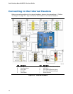
Connecting to the Front Panel Header
Before connecting to the front panel header, observe the precautions in "Before You
Begin" on page
25. See Figure 23, E on page 46 for the location of the multi-colored
front panel header.
Table 13 shows the pin assignments for the front panel header.
Table 13. Front Panel Header
Pin Description In/Out
Pin Description In/Out
Hard Drive Activity LED Power LED
1 Hard disk LED pull-up to +5 V
Out 2 Front panel green LED Out
3 Hard disk active LED Out 4 Front panel yellow LED Out
Reset Switch On/Off Switch
5 Ground 6 Power switch In
7 Reset switch In 8 Ground
Power Not Connected
9 Power Out 10 No pin
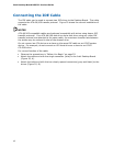
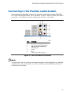
Connecting to the USB 2.0 Headers
Before connecting to the USB 2.0 headers, observe the precautions in "Before You
Begin" on page
25. See Figure 23, G on page 46 for the location of the three USB 2.0
headers.
Table 14 shows the pin assignments for each USB 2.0 header. Each USB
header can be used to connect two USB devices.
Table 14. USB 2.0 Header Signal Names
USB Port A USB Port B
Pin Signal Name Pin Signal Name
1 Power (+5 V) 2 Power (+5 V)
3 D- 4 D-
5 D+ 6 D+
7 Ground 8 Ground
9 Key 10 No Connection
Note: USB ports may be assigned as needed.
NOTE
Computer systems that have an unshielded cable attached to a USB port might not
meet FCC Class B requirements, even if no device or a low-speed USB device is
attached to the cable. Use a shielded cable that meets the requirements for a
full-speed USB device.