


Installing and Replacing Desktop Board Components
49
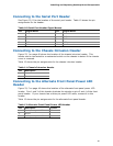
Connecting to the Serial Port Header
See Figure 23, D for the location of the serial port header. Table 10 shows the pin
assignments for the header.
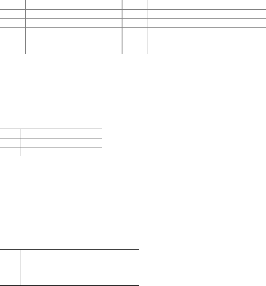
Table 10. Serial Port Header Signal Names
Pin Signal Name Pin Signal Name
1 DCD 2 RXD#
3 TXD# 4 DTR
5 Ground 6 DSR
7 RTS 8 CTS
9 RI 10 No Connection
Connecting to the Chassis Intrusion Header
Figure 23, J on page 46 shows the location of the chassis intrusion header. This
header can be connected to a mechanical switch on the chassis to detect if the chassis
cover is removed.
Table 12 shows the pin assignments for the chassis intrusion header.
Table 11. Chassis Intrusion Header
Pin Description
1 Intruder
2 Ground
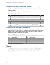
Connecting to the Alternate Front Panel Power LED
Header
Figure 23, F on page 46 shows the location of the alternate front panel power LED
header. Pins 1 and 3 of this header duplicate the signals on pins 2 and 4 of the front
panel header. If your chassis has a three-pin power LED cable, connect it to this
header.
Table 12 shows the pin assignments for the alternate front panel header.
Table 12. Alternate Front Panel Power LED Header
Pin Description In/Out
1 Front panel green LED Out
2 No pin
3 Front panel yellow LED Out