


PAGE 4 of 14
MODEL TI984 TELEPHONE INTERFACE 42004-071F
f:\standard ioms - current release\42004 instr. manuals\42004-071f.doc
05/03
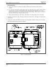
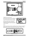
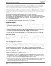
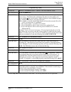
Figure 2. Termination Area
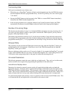
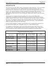
Telephone Line Connections
The TI984 should be connected to the Central Office (CO)
RJ11C jack from the telephone company or to a PBX with
the 14-foot RJ11 interconnect cable. See your telephone
company if a CO jack needs to be installed or extended.
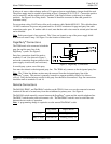
The connection outlined in Figure 3 is recommended
because it allows the use of all the available types of
incoming modes. If the call from the CO is to be directly
connected to the Page/Party
®
system, use the bypass feature
available on the PBX.
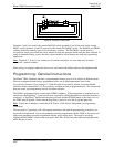
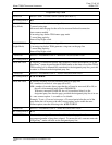
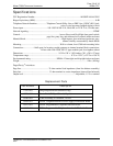
Power
The unit can be powered by 115 or 230 V ac (50 to 60 Hz), or 24 V dc. If using ac power, connect the ac
neutral wire (white) to terminal 6 and the ac hot wire (black) to terminal 2. See Figure 4. The earth
ground wire (green or green/yellow stripe) should be connected to terminal 4. Set the Power Selector
switch at the lower right of the power supply to the proper voltage setting (115 or 230 V).
Figure 4. Power Connections
Figure 3. Telephone Connections