TELEPHONE ACCESS MODULE
3 69-1352
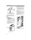
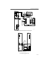
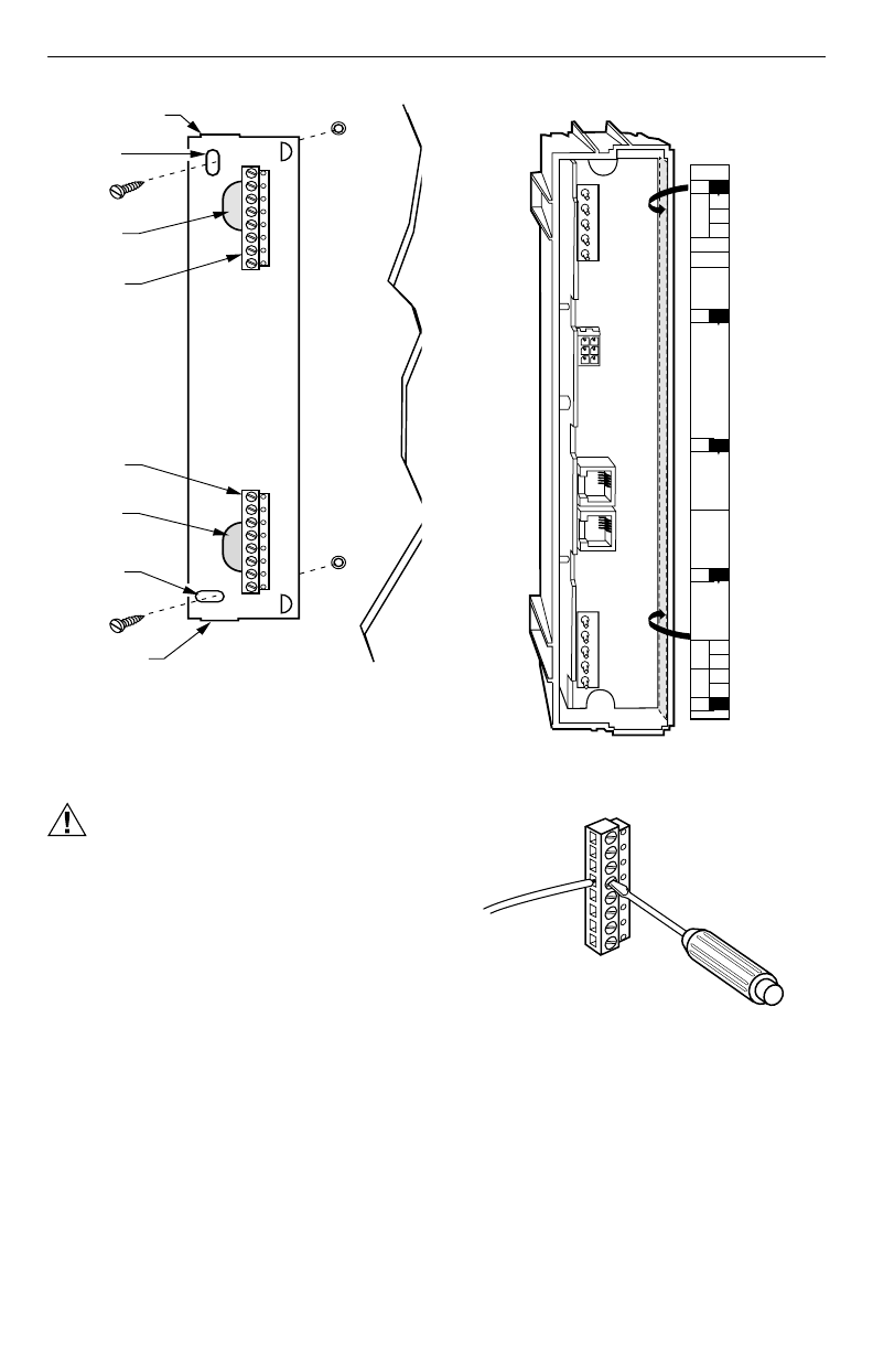
Fig. 4. Mounting W8735B subbase.
WIRING
CAUTION
Electrical Shock Hazard.
Can cause personal injury and equipment
damage.
Disconnect power before beginning installation.
1.
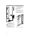
Locate the wiring label inside the telephone access
module. See Fig. 5.
2.
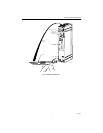
Loosen the terminal screws on the W8735B and
connect the system wires. See Fig. 6 through 9
and Table 2.
3.
Securely tighten each terminal screw.
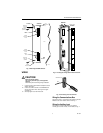
Fig. 5. Locating the wiring label inside the module.
Fig. 6. Connecting wires to terminals.
Wiring the Communications Bus
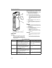
Connect terminals 1, 2, and 3 from the Telephone Access
Module to the other network devices. See Fig. 7.
Wiring the Auxiliary Input
Connect Aux1 and Aux2 terminals to an optional
normally open sensor contact, not included; see Fig. 7.
WIRING
HOLE
SUBBASE
WIRING
TERMINAL
BLOCK
MOUNTING
HOLE FOR
SUBBASE
WIRING
KNOCKOUT
MOUNTING
HOLE FOR
SUBBASE
WIRING
KNOCKOUT
M14779
WALL
ANCHORS
(2)
WALL
MOUNTING
SCREWS (2)
WIRING
TERMINAL
BLOCK
WIRING
HOLE
A
con.
1
2
3
Aux1
Aux2
B
con.
C
con.
D
con.
Line
in
Phone
out
M14778
Line in
Phone out
Ph1
Ph2
Ln1
Ln2
WIRING LABEL
ON INSIDE
OF MODULE
MODULE
WIRE
M14803
TERMINAL BLOCK
SCREW
DRIVER


