


TELEPHONE ACCESS MODULE
69-1352 2
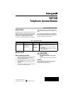
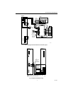
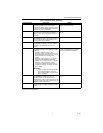
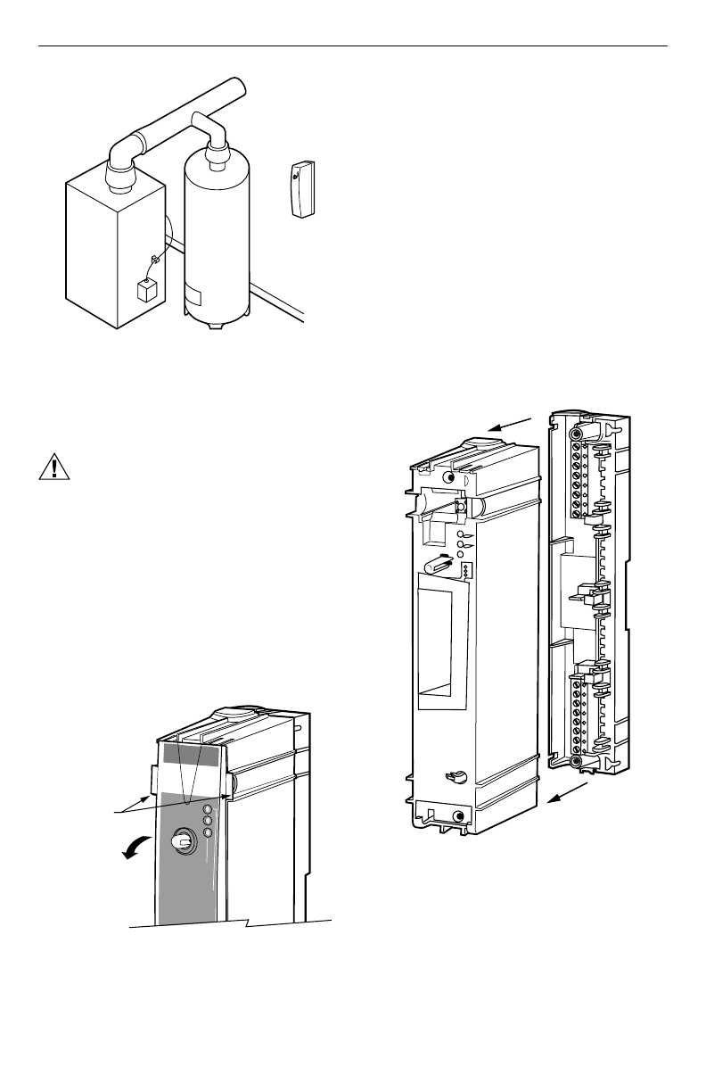
Fig. 1. Locating W8735B in equipment room.
Mounting W8735B Telephone Access
Module
CAUTION
Equipment Mounting Damage Hazard.
Can damage W8735B when mounted inside
HVAC equipment.
Mount W8735B outside of any HVAC equipment,
where access to main telephone line is available.
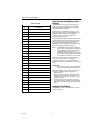
1.
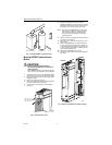
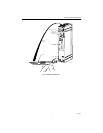
Unsnap the front cover from the W8735B by grasp-
ing the tabs near the top of the module. See Fig. 2.
2.
Swing the front cover down and lift it slightly to dis-
engage the hinges.
3.
Remove the cover and set aside.
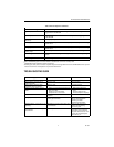
4.
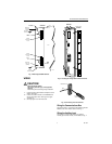
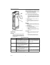
Remove the subbase by slowly pulling the subbase
from the module housing. See Fig. 3
.
5.
Locate the two mounting holes on the subbase.
See Fig 4.
Fig. 2. Removing front cover.
6.
Position the subbase on the wall. Level the
W8735B for appearance only; the device functions
properly even when not level. Use a pencil to mark
the position of the mounting holes on the wall.
NOTE: The wiring for the W8735B can be fed through
the back of the subbase or through the knock-
outs at the top and bottom of the subbase. If
using the knockouts, skip steps 7 and 8 and
proceed to step 9.
7.
Mark the center of one or both wiring holes located
in the back of the subbase.
8.
Drill a 5/8 or 3/4 in. hole, where marked, for insert-
ing the wires.
9.
Remove the W8735B from the wall and drill 3/16
in. holes in the wall (if drywall) where marked. For
firmer materials such as plaster or wood, drill 7/32
in. holes. Gently tap the anchors, provided, into the
holes until flush with the wall.
10.
Reposition the W8735B over the holes.
11.
Loosely insert the screws into the holes and tighten
the screws.
Fig. 3. Removing subbase from module housing.
M14800
WATER HEATER
W8735B
FURNACE OR BOILER
a
u
x
i
l
i
a
r
y
i
n
p
u
t
b
a
t
t
e
r
y
M14801
o
n
lin
e
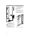
momentary flash - ok
steady flash - replace
on continuously - replace
a
u
x
ilia
ry
in
p
u
t
b
a
tte
ry
FRONT COVER TABS
GRASP TABS AND
SWING COVER DOWN
M14802
SUBBASE
MODULE