


7
6. Connector Pin Assignment
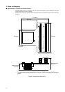
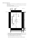
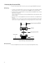
The signal of Evaluation MCU with which it was carried on the adapter board is connected to YQ-
PACK(the same assignments as production MCU) via the probe cable connector(B1,B2) on a header
board.
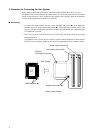
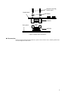
An adapter board and a header board are connected to an emulator main part by the attached flat ca-
ble (It is used standard 2 or two long.)connector.
Please check the hardware manual of an emulator or an adapter board about reference of the connec-
tion method.
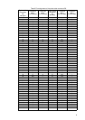
■ Pin Assignment
Tables 1 and 2 list the pin assignments among the flat cable connector, the evaluation MCU on the
adapter board, and the production MCU.
For details on the names of signal conductors of the evaluation MCU, refer to the hardware manual
for the adapter board.
Comments in the tables are given below.
*1 : Connected to the main power supply of the evaluation MCU.
*2 : Connected to the main power supply (Vcc) of the production MCU. The connection pin num-
bers are 15 and 90.
*3 : Connected to the ground of the evaluation MCU.
*4 : Connected to the ground (Vss) of the production MCU. The connection pin numbers are 16,
44 and 91.
- : Unconnected pin (left open).