


8
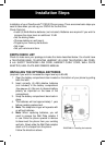
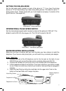
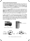
Wall Mount Use
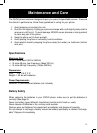
1. Slide the handset hanger tab out and reverse it’s position (rotate it 180 degrees).
Before sliding it back into place FLIP OVER the TAB so that the hook points up and
away from the base (See diagram #4) This will keep the handset from falling out of
the cradle when is mounted on the wall.
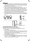
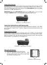
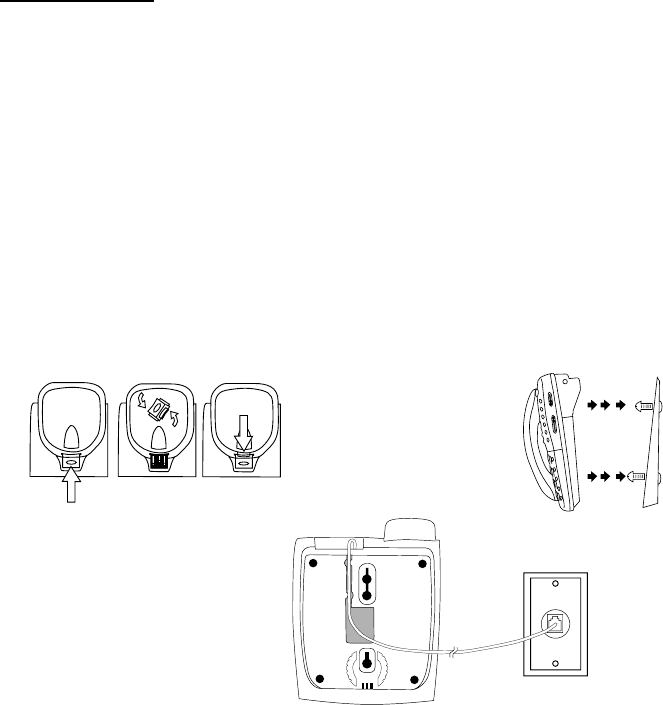
2. Plug the 8 in phone cord into the telephone jack on the CSC40.
3. Insert the Wall Plate adapter (See diagram #5). Which will snaps into place. The
phone line should run underneath the wall plate adapter through the center tab.
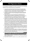
4. Plug the phone cord into the wall jack, then holding the phone slightly above the
mounting screws on the wall jack, push the phone against the mounting screws so
they are hooked into the upper and lower key-hole slots on the back of the phone.
Slowly slide the phone down until it snaps into place (See diagram #6).
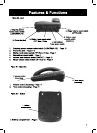
5. Connect the handset coil cord (curly cord) to the handset and to the telephone.
6. Lift the handset and listen for a dial tone. If you hear a dial tone, your phone is ready
to use. If there is no dial tone, check all your cords to make sure they are plugged in
securely.
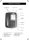
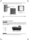
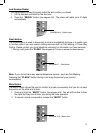
PROGRAMMING MEMORY DIAL BUTTONS
Your CSC40 Phone holds 12 programmed Memory Dial Buttons.
To program your one-touch memory dial buttons please follow instructions below:
1. Lift the handset.
2. Press the PROG button (See diagram #7).
3. Press one of the 12 Memory Dial buttons (M1 - M12) located on top of the phone
(See diagram #8). Each button can be programmed (or reprogrammed using the
same procedure) for a phone number up to 21 digits long.
4. Using the keypad, dial the number you would like to save, including 1 and the area
code (if applicable).
(See diagram #9).
5. Press the PROG button again (See diagram #7).
6. To register your stored phone numbers, use the erasable phonebook card located
on the top of your phone. IMPORTANT: The phonebook card is non-removable.
Simply use a clean pencil eraser to make changes.
DIAGRAM #4 – Reversing the hook
DIAGRAM #5 –Wall plate installation
DIAGRAM #6 – Wall installation