


3-8
Cisco Unified IP Phone Services Application Development Notes
OL-20949-01
Chapter 3 CiscoIPPhone XML Objects
XML Object Definitions
<Depth>Number of bits per pixel</Depth>
<Data>Packed Pixel Data</Data>
<SoftKeyItem>
<Name>Name of the softkey</Name>
<URL>URL of softkey</URL>
<Position>Numerical position of the softkey</Position>
</SoftKeyItem>
</CiscoIPPhoneImage>
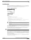
Note The 6900 series IP phones does not display the Title and Prompt menu fields at the same time.
If both Title and Prompt fields are defined at the same time, then these phones display only the
Prompt field.
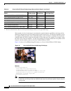
The CiscoIPPhoneImage object definition includes two familiar elements: Title and Prompt. These
elements serve the same purpose as they do in the other CiscoIPPhone XML objects. The
Title displays
at the top of the page, and the
Prompt displays at the bottom.
Use
LocationX and LocationY to position the graphic on the phone display. Position the upper, left corner
of the graphic at the pixel defined by these two parameters. Setting the X and Y location values to (0, 0)
positions the graphic at the upper, left corner of the display. Setting the X and Y location values to (-1,
-1) centers the graphic in the services pane of the phone display.
Use
Width and Height to size the graphic. If the values do not match with the pixel stream specified in
the
Data field, results will be unpredictable incorrect.
Depth specifies the number of bits per pixel. Cisco Unified IP Phones support a maximum value of 2. A
bit depth of 1 is black and white.
The
Data tag delimits a string of hexadecimal digits that contain the packed value of the pixels in the
display. In the Cisco Unified IP Phone, each pixel has only four possible values, which means that you
ca
n pack four pixels into a single byte. A pair of hexadecimal digits represents each byte.
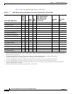
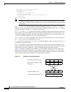
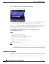
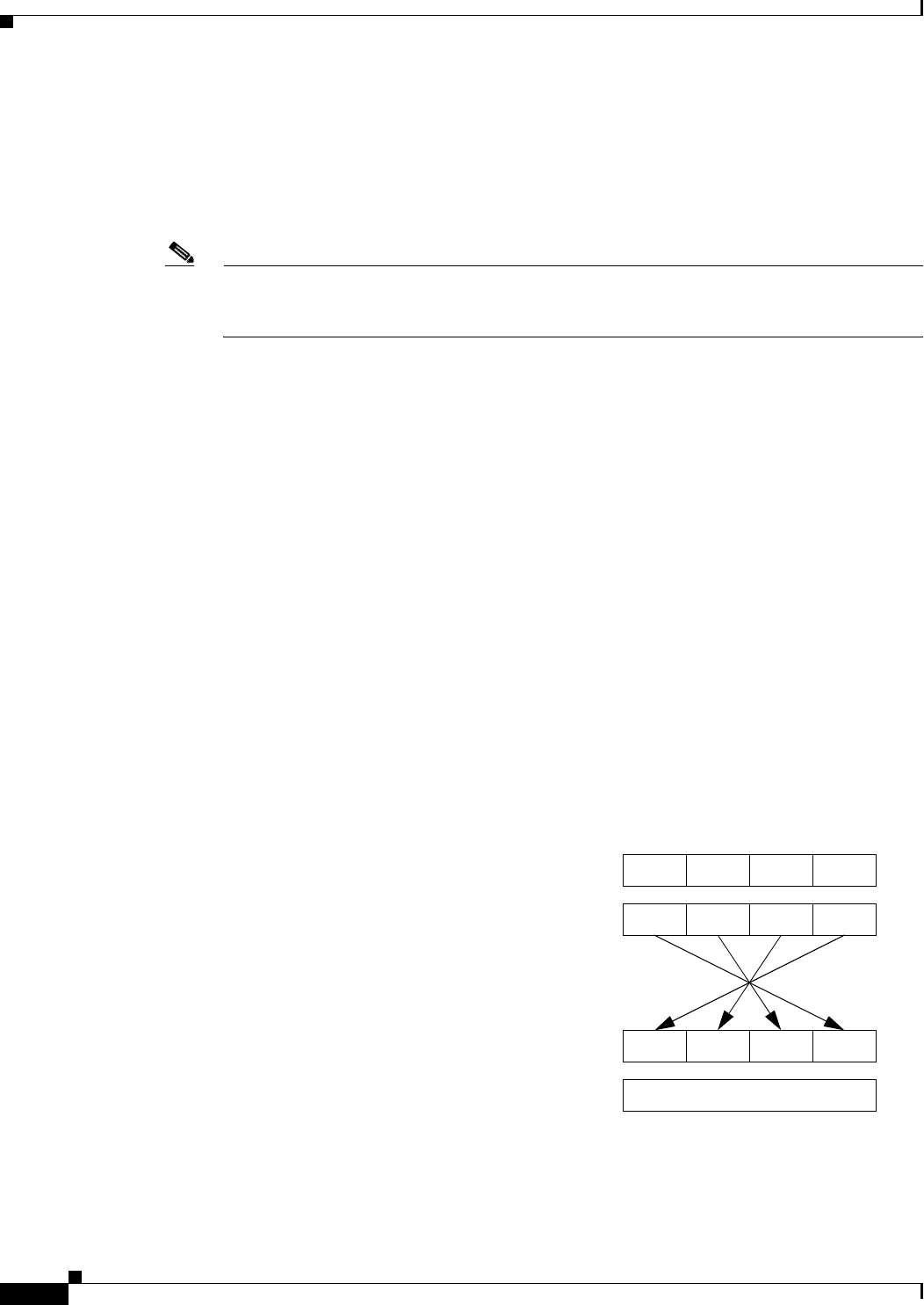
Figure 3-3 p
rovides an example of the mechanics of pixel packing. Scanning from left to right in the
display, the illustration shows the process for packing consecutive pixel values of 1, 3, 2, and 0. First,
th
e pixels get converted to 2-bit binary numbers. Then, the binary pairs get re-ordered in sets of four to
create a single re-ordered byte, which two hexadecimal digits represent.
Figure 3-3 Packed Pixel Translation Example
Pixel values original sequence 1320
Pixel values converted to 2-bit
binary pairs
01 001011
Re-ordered binary pairs
2D
1-byte packed hexadecimal value
00 0110 11