


12
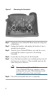
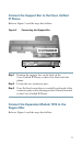
Step 3 Plug one end of the second interface cable into the AUX
jack with the “out” icon underneath on the first
Expansion Module (the one closest to the phone).
Step 4 Plug the other end of the second interface cable into the
AUX jack with the “in” icon underneath on the second
Expansion Module (the one next to the first Expansion
Module).
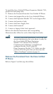
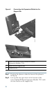
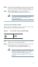
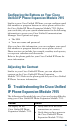
Connect the Power Supply Unit
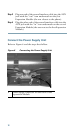
Refer to Figure 6 and the steps that follow.
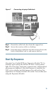
Figure 6 Connecting the Power Supply Unit
1
Power supply connector on the back of the
Expansion Module