


11
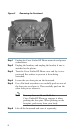
Step 3 Insert the hooks into the slots and then rotate the top
of the Cisco
Unified IP Phone Expansion Module 7915
into the support bar so that it rests flush with the bar.
Step 4 Tighten the thumbscrew on the back of the
Cisco
Unified IP Phone Expansion Module 7915.
Note If you are installing two Expansion Modules,
repeat Steps 2, 3, and 4 for the second
Expansion Module.
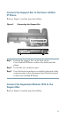
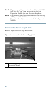
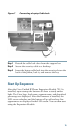
Connect the Interface Cable
Refer to Figure 5 which depicts the “in” and “out” icons on the
AUX jacks, and to and the steps that follow.
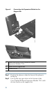
Figure 5 “In” and “Out” Icons on the AUX Jacks
In icon Out icon
Step 1 Plug one end of the interface cable into the jack labeled
AUX on the Cisco
Unified IP Phone.
Step 2 Plug the other end of the interface cable into the AUX
jack with the “in” icon underneath on the
Cisco
Unified IP Phone Expansion Module 7915.
Note If you are installing a second Cisco Unified
IP
Phone Expansion Module 7915, continue
with Steps 3 and 4. Otherwise go to the
“Connect the Power Supply Unit” section on
page 12.