


Configure Dial Peers
VC-28
Voice, Video, and Home Applications Configuration Guide
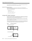
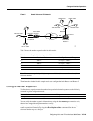
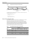
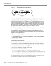
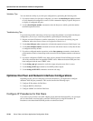
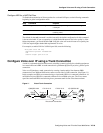
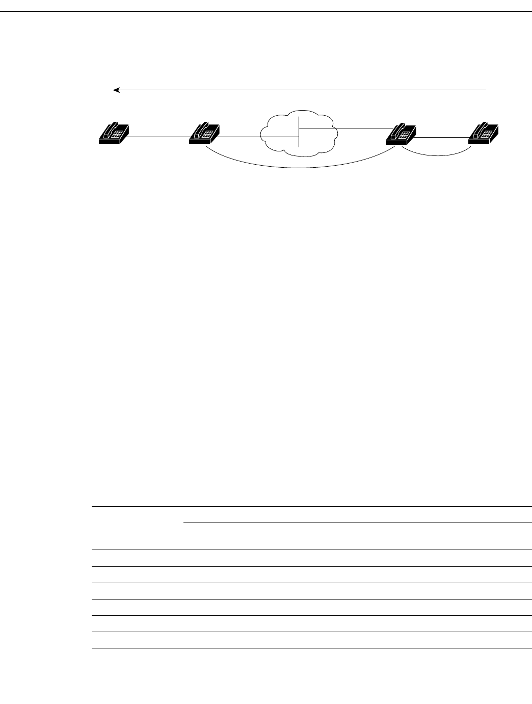
Figure 9 Outgoing Calls from the Perspective of POTS Dial Peer 2
To complete the end-to-end call between dial peer 1 and dial peer 4 as illustrated in Figure 9, enter
the following commands on router 10.1.1.2:
dial-peer voice 4 pots
destination-pattern 1310555....
port 1/0/0
dial-peer voice 3 voip
destination-pattern 1408555....
session target ipv4:10.1.2.2
Create a Peer Configuration Table
There is specific data relative to each dial peer that needs to be identified before you can configure
dial peers in Voice over IP. One way to do this is to create a peer configuration table.
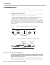
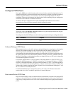
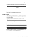
Using the example in Figure 5, Router 1, with an IP address of 10.1.1.1, connects a small sales
branch office to the main office through Router 2. There are three telephones in the sales branch
office that need to be established as dial peers. Router 2, with an IP address of 10.1.1.2, is the primary
gateway to the main office; as such, it needs to be connected to the company’s PBX. There are four
devices that need to be established as dial peers in the main office, all of which are basic telephones
connected to the PBX. Figure 5 shows a diagram of this small voice network.
Table 6 shows the peer configuration table for the example illustrated in Figure 5.
Table 6 Peer Configuration Table for Sample Voice Over IP Network
Commands
Dial Peer
Tag Ext Dest-Pattern Type Voice Port session target CODEC QoS
Router 1
1 6.... +1408116.... POTS
10 +1729555.... VoIP IPV4 10.1.1.2 G.729 Best Effort
Router 2
11 +1408116.... VoIP IPV4 10.1.1.1 G.729 Best Effort
4 2.... +1729555.... POTS
S6614
(408) 555-4000
Dial peer 1
Dial peer 2
Dial peer 3
VoIP call leg
POTS call leg
Dial peer 4
(310) 555-1000
10.1.2.2
SourceDestination
10.1.1.2
Voice port
1/0/0
Voice port
1/0/0
IP cloud