


5
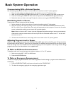
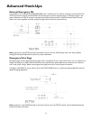
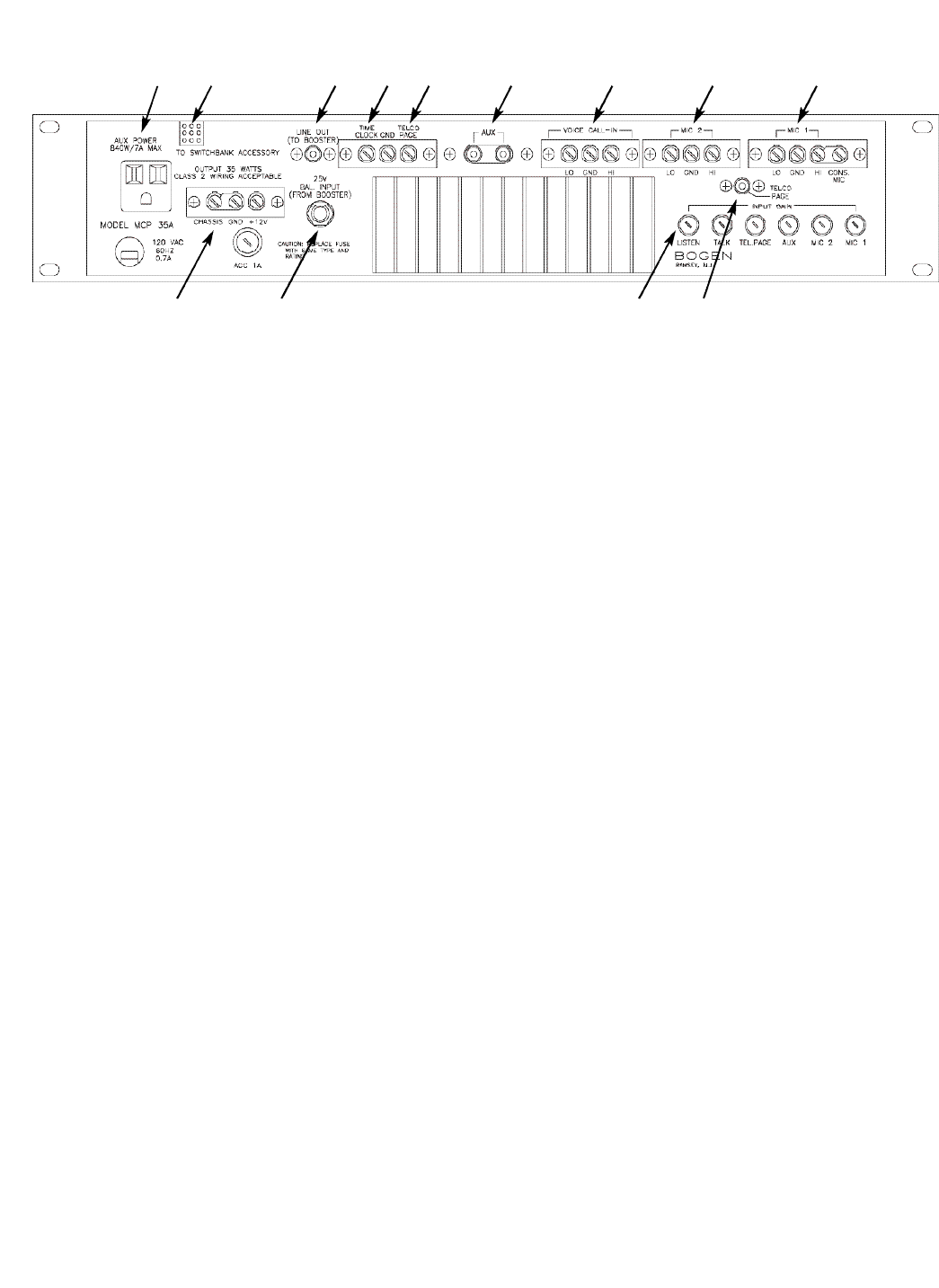
MCP35A Rear Control Panel
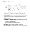
1. MIC 1 - Connections for an external mic (MIC 1).When the PROGRAM DISTRIBUTION button MIC 1 is pressed,
the microphone connected here becomes active.As shipped from the factory, a link is installed between the HI and
CONS MIC terminals.This makes the CONSOLE MIC act as MIC 1. When the link is removed,an external micro-
phone can be connected to act as MIC 1 and the CONSOLE MIC will no longer be active when the MIC 1 button
is pressed.
Note: The CONSOLE MIC is always used when the EMERGENCY PAGE button is pressed and when using the green
INTERCOM PUSH-TO-TALK button (the user cannot change this).The external mic must be a low-impedance
balanced mic (phantom power is also available for condenser mics).
2. MIC 2 - Connections for an external mic (MIC 2).When the PROGRAM DISTRIBUTION button MIC 2 is pressed,
the microphone connected here becomes active. The external mic must be a low-impedance balanced mic (phantom
power is also available for condenser mics).
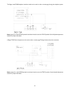
3. VOICE CALL-IN - Allows retro fitting to older voice call-in systems with call-in switches connected in parallel.
When a call-in switch is activated, an intercom channel is opened to the MCP35A control panel speaker so that the
caller can announce verbally which room is calling. Systems that use this style of call-in will not see an annunciator
light on the SBA225 room selector panel.
4. AUX - A high-impedance unbalanced input for auxiliary music sources.This input only becomes active when the
PROGRAM DISTRIBUTION button AUX button is pressed.
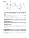
5. TELCO PAGE - Shorting the TELCO PAGE terminal to GND activates a page from either MIC 2 or the TELCO
INPUT (selected by an internal jumper).
6. TIME CLOCK - Shorting the TIME CLOCK terminal to GND produces a tone signal in all speakers.
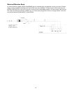
7. LINE OUT - Provides an input signal that can be connected to the input of an external booster amp.Works in
conjunction with the 25V BAL INPUT to allow replacement of the MCP35A control panel’s built-in amplifier with a
higher power amplifier.
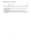
8. SWITCHBANK CONNECTOR - SBA225 switchbank is connected to the MCP35A panel through this connector.
9. AUX POWER - An AC power outlet for auxiliary equipment.
10. 12V POWER TERMINALS - Chassis, ground, +12V DC supply, 750mA for powering up to 3 SCR25A modules.
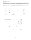
11. 25V BAL INPUT - The output of an external booster amp is connected at this 1/4” stereo phone jack.Works in
conjunction with the LINE OUT connector (see #7 above).
12. INPUT GAIN - Input level adjustments for all input sources.
13. TELCO PAGE - Alternate input for MIC 2 allows connection of Bogen model WMT1A for providing a 600-ohm
balanced telephone input.
123456789
10 11 12 13