


Extension
■
Ringing voltage: +5VDC, -140 VDC peak to peak; trapezoidal wave shaping
Jack
On a PARTNER Plus 220V System: +5VDC, -150 VDC peak to peak
Specifications
■
35- to 38-Volt talk battery
■
Ringing frequency: 20 Hz
PAGE Jack
■
Draws current on inner wire pair
Specifications
■
Provides contact closure on outer wire pair
■
600 Ohm impedance
SMDR Output
■
1200 baud
Format
■
No parity
■
8 data bits
■
2 stop bits
Environmental
■
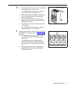
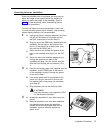
Mount on a wall at least 2 feet (0.6 meters) from the floor (wall mounting required)
Requirements—
Control Unit
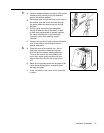
■
Locate within 5 feet (1.5 meters) of the network interface jacks and an electrical outlet not
controlled by a switch, using supplied 7-foot (2.1-meter) cords
■
Operating temperature 32° to +104°F (0° to +40°C), not in direct sunlight
■
Humidity 15%–90%, noncondensing
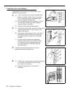
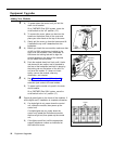
■
For proper ventilation and easy replacement of modules, provide at least 6" (15.2cm) clearance
at the top and sides and 2 feet (0.6 meters) at the front and bottom of the control unit.
■
Locate in an area free of excess moisture, corrosive gases, dust, and chemicals
Electrical
■
90–130 VAC, 50–60 Hz, 3-prong outlet separate ground, separately fused at 15 Amps
Requirements
On a PARTNER Plus 220V System: 180–264 VAC, fused at 10 Amps
■
Outlet must not be controlled by an on/off switch
■
Grounding to comply with Underwriters Laboratories (UL) 1459:
A.
An insulated grounding conductor that is not smaller in size and equivalent in insulation
material and thickness to the grounded and ungrounded branch circuit supply conductors,
except that it is green with or without one or more yellow stripes, is to be installed as part of the
circuit that supplies the product or system.
B.
The grounding conductor mentioned in item A is to be connected to ground at the service
equipment.
C.
The attachment-plug receptacles in the vicinity of the product or system are all to be of a
grounding type, and the grounding conductors serving these receptacles are to be connected
to earth ground at the service equipment.
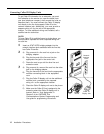
Requirements for
Installation of a telephone or other standard (tip/ring) device in another building requires the
Out-of-Building
following In-Range Out-of-Building (IROB) protectors to protect the control unit and device from
Extensions
electrical surges:
■
System phone: two AT&T IROB protectors
■
Standard device: one AT&T IROB protector plus one carbon block protection
Wiring
■
System phones: AT&T SYSTIMAX® Bulk Nonplenum (DIW) cable, AT&T SYSTIMAX Bulk
Plenum (HALAR/HALAR) cable, or at least 2-pair (4-wire) star (“home run” not “loop”)
■
Other standard telecommunications equipment (single-line phones, fax machines, answering
machines, etc.): 1-pair (2-wire) mounting cords (AT&T D2R mounting cords recommended)
■
Bridging adapter: AT&T 267F2
■
Range: 1,000 feet (305 meters) for system phones: 3,000 feet (915 meters) for standard
devices
22
Specifications