


2
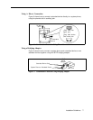
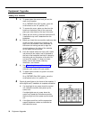
A)
Gray Jack
White Jack
B)
C)
3
A)
B)
C)
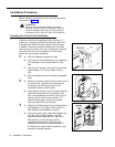
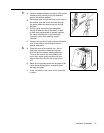
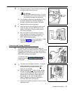
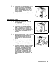
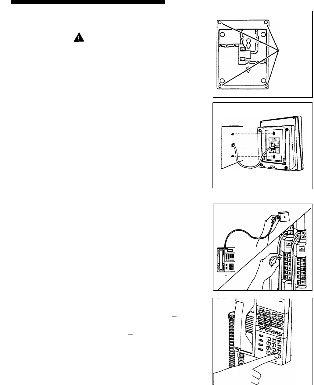
Unscrew the phone’s four mounting screws and lift
the base of the phone off the top.
CAUTION:
Do not touch electrical circuitry. To do so
will expose you to a risk of electrical shock
and possibly damage the equipment.
Turn the base of the phone upside down so that
the phone base can be mounted parallel to
the wall—and then place it back on the base.
Replace the four mounting screws.
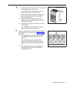
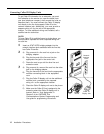
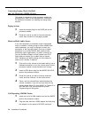
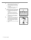
Insert the phone cord through the center of the
stand and plug it into the WHITE jack on the
bottom of the phone. Plug the other end into
the modular wall jack.
Mount the phone on the wall plate using the
screw keyholes on the base of the stand. For
proper mounting, the wall plate must be an
AT&T 630B connecting block.
Connect the handset cord as described in “Desk
Mounting,” Step 1A, and label the button
sheet as in Steps 3A and 3B.
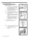
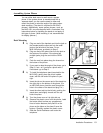
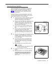
Connecting and Testing Telephones
To connect a phone, plug the modular telephone
1
mounting cord into a modular wall jack or directly into a
206 module extension jack. (If you are connecting a
standard phone and its mounting cord is loose, try an
AT&T D2R mounting cord instead.)
To install two phones (or other devices) on a single
extension jack, see “Combination Extensions” earlier
in this guide
2
A)
B)
C)
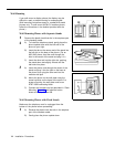
Test the phone for proper operation. To test the
power and lights on a system phone: while
the phone is idle, press and hold the [
# ]
button for five seconds.
Before releasing the [
# ] button, lift the handset.
All lights should light, the ringer should sound,
and (on the MLS-34D, MLS-18D, or MLS-12D
phones only) a test pattern should appear on
the display. (If not, call the appropriate
support telephone number as instructed on
the inside front cover of this guide.)
Replace the handset; the phone is now in normal
operating mode.
Mounting
Screws
Installation Procedures
15