


Section 5 TutorialSection 5 Tutorial
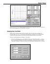
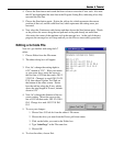
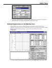
Now let’s get familiar with the Tool Path View Box. Here are some important features:
Red Lines - Represent the entire tool path of the part to be cut.
Green Dot - Represents Program Zero, the origin of any G-Code program.
Light Blue Dot - Represents Machine Zero, also called Home.
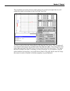
Yellow Dot (not shown here) - Represents the current XY position of the machine
tool during the cutting (or animating) operation.
Blue Lines (not shown here) - Represent the portion of the tool path already cut.
Dotted Lines - Represent a rapid move.
Solid Lines - Represent a feedrate move
Blue Tool - Represents the current Z position of the machine tool during the
machining (or animating) operation.
Light Blue Lines - Represent the borders of the machine tool envelope.
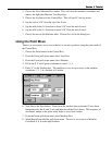
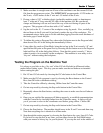
Animating the G-Code File
Now we are ready to animate the tool path on the screen to verify the program.
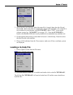
1. Choose the Set button next to the Program label, then choose Zero All in the dialog box
that immediately follows. LC sets all three program coordinates to 0. This simulates
the tool being in the correct position before the program begins.
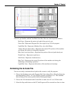
2. Choose the G-Code button in the Control Box to make sure LC is in G-Code mode.
3. Select the Step radio button so the G-Code Program will be executed one line at a time.