


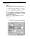

Section Section 33 Initial SetupInitial Setup
2727
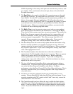
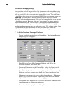
revolution, a 0.9° Stepper Motor will have 400 full steps per revolution,
and so on. This number is a characteristic of the stepper motor and is
independent of the Stepper Motor Driver or the Step Mode.
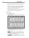
5. Gear Ratio - The ratio of the number of stepper motor revolutions to
drive screw revolutions due to any gears or pulleys between them. If it is
a direct drive, enter 1 in this box.
6. Screw Thread - The number of turns per inch of the helical drive screw
for each axis. For example, a single threaded, 0.05” pitch screw would
have 20 turns per inch.
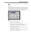
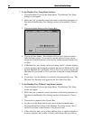
7. There are also general settings unique to each machine tool. These are
described below. Once you determine the correct value for each general
setting, enter it in the appropriate text box.
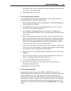
8. Axis Length - Sets the length of travel of each axis of your machine tool.
You may want to define the axis length slightly smaller than the values
published by the machine tool manufacturer. This will leave some room
for error. Enter these figures in the Axis Length text boxes.
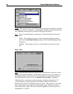
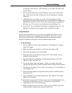
9. Motor Polarity - Depending on how a motor is wired, the same signal
from the Stepper Motor Driver can turn it clockwise or counter clockwise.
Use the jog buttons to make sure that a positive move in each axis on the
screen corresponds to a positive move in each axis on the machine tool.
Note that the direction of movement is defined as the direction of the tool
relative to the table. For example, a positive X move in the program (tool
movement to the right) will result in table movement to the left. If any
direction is incorrect, change the motor polarity from Positive to Negative
(or vice-versa) to reverse the correspondence between the software and
machine tool.
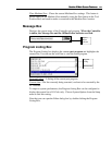
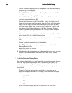
10. Machine Envelope Home End - The end of an axis at which the optional
home switch is installed. This determines the placement of the origin of
the Machine Tool Envelope (Machine Zero) once home is set.
11. Home Switch Offset - The distance each axis backs away from the home
switch after the switch is closed during homing.
12. Backlash - Sets the amount of backlash for each axis. See the “Setting
Backlash” section below for more information.
13. Comp – Tells LC whether or not to use backlash compensation for all
direction changes. Leave this checkbox unchecked for now. It is
discussed in the “Setting Backlash” section below.
14. Tool Change Position – The position in Machine Coordinates where the
machine will move when given the G28 command in the program.
15. When you are done entering the correct information, choose the OK
button.