


- 4 -
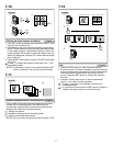
3
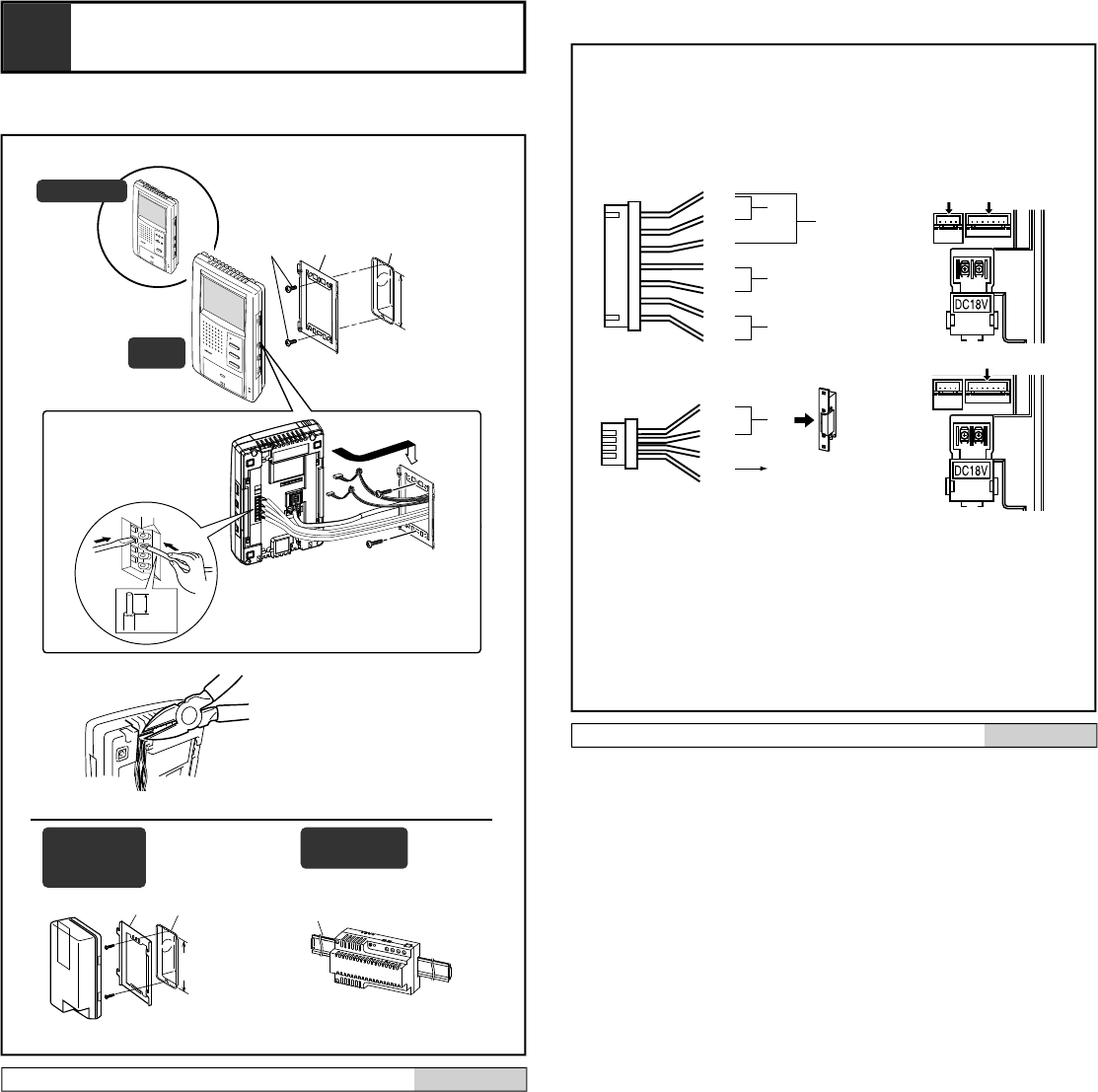
MOUNTING
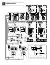
3-1
83,5 mm
(3-5/16")
[3][2][1]
[4]
83,5 mm
(3-5/16")
[3][2]
PS-1820DIN
PS-1810DIN
1
2
9mm
(3/8")
JB-2MD
TALK
JB-2MED
TALK
CALL
MONITOR
REC
PLAY
SET
JB-2MED
JB-2MD
JB-2HD
PS-1820
PS-1820S
PS-1820UL
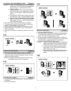
Mounting
English
[1] Screws (x2)
[2] Mounting bracket
[3] 1-gang box
[4] Din rail
1. Press the RELEASE button (to insert or remove the wire).
2. Insert the cable into the terminal.
NOTES: When a 1-gang box is not installed, the cable can
be surface-run to the top or bottom of the unit. Cut
the cable inlet to allow passage of the wiring into
the unit.
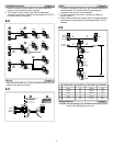
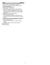
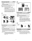
3-2
#2
#1
E
SW
P
b2
b1
V -
V +
[2]
(BR)
(RD)
[5]
[6]
(OG)
(YE)
(RD)
(BR)
(OG)
(YE)
(GR)
(BL)
(PR)
[4]
[3]
[1]
#2 #1
#1
JB-2M(E)D
JB-2HD
c2
c1
L
L
PR: Violeta
BL: Azul
GR: Verde
YE: Amarillo
OR: Naranjo
RD: Rojo
BR: Marrón
PR: Paars
BL: Blauw
GR: Groen
YE: Geel
OR: Oranje
RD: Rood
BR: Bruin
PR: Lila
BL: Blau
GR: Grün
YE: Gelb
OR: Orange
RD: Rot
BR: Braun
PR: Violet
BL: Bleu
GR: Vert
YE: Jaune
OR: Orange
RD: Rouge
BR: Brun
PR: Purple
BL: Blue
GR: Green
YE: Yellow
OR: Orange
RD: Red
BR: Brown
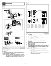
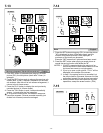
Options
English
[1] Foot switch
Connect a locally available pedal foot switch to PURPLE
and BLUE wires (dry closure contact).
[2] Manual Press-to-Talk restriction
Short PURPLE and GREEN wires together to prevent
manual TALK button operation.
[3] Selective door release
Please refer to the wiring diagram #9 for detail
connection.
[4] Video output to video monitor, video switcher, etc.
(NTSC,1 Vp-p/75Ω)
[5] Single door release
Connect BROWN and RED wires from connector #2 to a
single door release (or to the RY-3DL as shown on the
wiring diagram).
[6] Sensor (JB-2MED only)
NOTES: 1. For JB-2HD, only functions [1] and [2] are
available.
2. Cut off unused wires and insulate the ends to
prevent shorting.
3. Provide a box deep enough to accommodate all
cables including options.