- 15 -
5-1
English
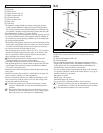
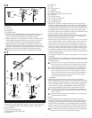
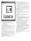
Wiring
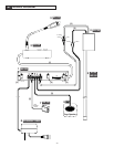
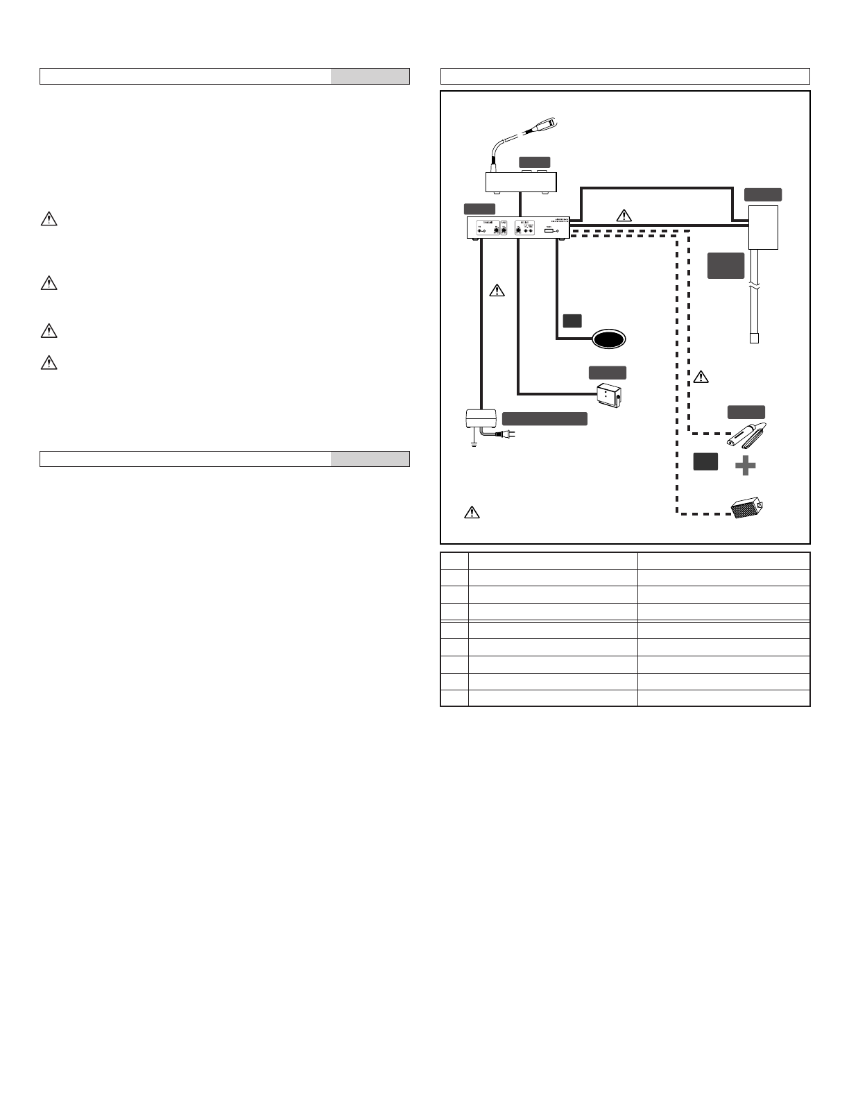
1. Main unit MU-100
2. Operation unit OU-100
3. Gooseneck microphone IME-100
4. Driver unit DR-100
5. Acoustic I/O tube AI-100 and acoustic tube IAX-100
6. Power supply adapter PS-2420UL/2420S
7. Sensor ISE-100
8. Paging speaker (option)
Suitable paging speakers have 4 to 6 Ω impedance and rated
input of 3W or more, with a maximum input of 6W or more.
[1] Special connection cord for operation unit and main unit
(approximately 2m,6'6").
Be sure to insert the cables to the correct polarity.
[2] Microphone cable: Ø0.65 mm (22AWG) to 1.2 mm (16AWG)
2-conductor shielded cable
Be sure to insulate the joints of the cable.
[3] Speaker cable: Ø0.9 mm (19AWG) to 1.2 mm (16AWG) cable
Be sure to insulate the cable splices.
[4] Wire Clamp
[5] Connection cord (approximately 3.5m, 11'5")
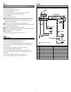
Wiring distance
5-2
English
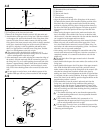
Cable layout
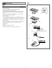
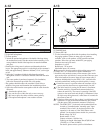
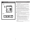
1. Use the special cable provided with the operation unit to
connect the operation unit with the main unit.
2. Receive input microphone cable layout
•Use a 2-conductor shielded cable with a high shielding effect.
•Splice the cable from the microphone to the terminal block on
the main unit.
•Be sure to splice the cable with the correct polarity.
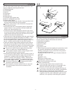
3. Transmit output speaker cable layout
•Use a cable of Ø0.9 mm (19AWG) specification or more.
•Splice the cable from the speaker to the terminal block of the
main unit.
•A twisted pair cable is suitable for the speaker.
•Be sure to splice the cable with the correct polarity.
5-3
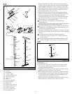
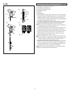
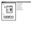
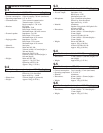
Ø0.65~1.2 mm AWG22~AWG16
A 20 m (max.) 66'(max.)
A' 20 m (max.) 66'(max.)
D 20 m (max.) 66'(max.)
Ø0.9~1.2 mm AWG19~AWG16
B 20 m (max.) 66'(max.)
B' 20 m (max.) 66'(max.)
C 20 m (max.) 66'(max.)
E 20 m (max.) 66'(max.)
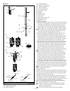
Page Speaker
MU-100
OU-100
DR-100
AI-100
IAX-100
PS-2420UL / 2420S
IME-150
ISE-100
External Speaker
C
A
(
Mic
)
A'
(
Mic
)
B
(
Speaker
)
DE
OP
OP
B'
(
Speaker
)
: Use the shield cable.


