- 11 -
4-10
English
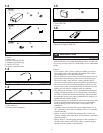
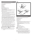
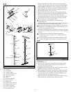
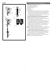
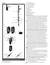
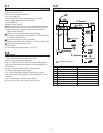
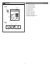
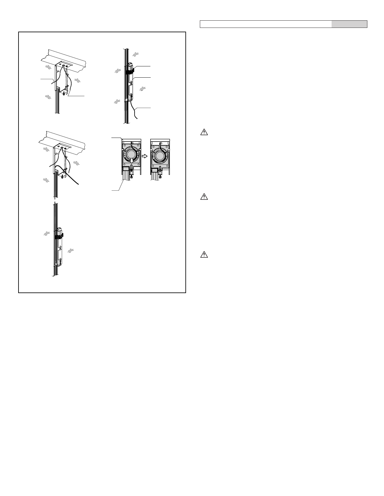
Acoustic interface wiring
[1] Speaker cable from main unit
[2] Microphone cable from main unit
[3] Temporary installation jig
[4] Acoustic I/O tube main unit
[5] Microphone cord
[6] Chassis
[7] Cord groove
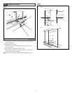
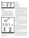
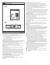
1. Pull the transmit output speaker cable and receive microphone
input cable that come from the main unit on the operator side
through the chassis cable hole in the driver main unit that is
fixed to the glass. Cut the cables that have been pulled through
at a length of approximately 20cm (3/4").
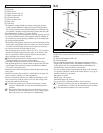
2. Use the jig to temporarily install the main unit of the acoustic
I/O tube in the fixing base groove at the specified position.
When installing the fixing base in the vicinity of the
architectural sash, temporarily install the acoustic I/O tube on
the side opposite to the architectural sash.
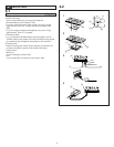
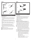
3. As shown in the diagram, while inserting the microphone cord
that protrudes from the bottom of the temporarily installed
acoustic I/O tube main unit upward into the cord groove of the
fixing base, position the cable until it is in the center of the
driver unit chassis. Cut the fixed cord so there is an excess
length of approximately 30cm (1-1/4").
Use the cord groove on the far side from the side where the
acoustic I/O tube is temporarily installed. If the groove on the
far side is used then the cord will fit smoothly when the
acoustic I/O tube is fixed into the fixing base.
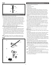
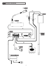
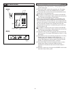
4. Return the removed driver main unit to the original position on
the chassis, put into the highest slide position, and lightly fix
with the specified screw. Lay out the microphone cord in the
space between the chassis and the driver main unit.
Pull the cables towards the upper side of the driver (ceiling
side) when returning the driver main unit.
12
43
[1]
[2]
[3]
[4]
[5]
[6]
[7]


