


Pg. 2
PS-2410LC
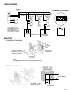
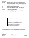
WIRING DIAGRAM:
(Entrance panel(s) not shown)
Common
Bus Line
R1
R2
+
-
GF-BC
+
-
R1
R2
C
CE
K
KE
GFO-1DL
R1
R2
C
CE
K
KE
GFO-1DL
R1
R2
C
CE
K
KE
GFO-1DL
*Optional Features
Red
Blk
Wire junction
point**
**Distribution point can be
any type of terminal strip,
punch down block, or suitable
wire connection point for
multiple bus lines of stations.
Up to 20 GFO-1DL's can be
run on each bus line.
Doorbell
button*
KE K CE C R2 R1
TERMINAL LOCATIONS:
GFK-PS Panic
Call Switch*
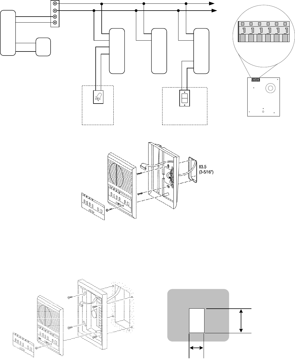
WALL
6-1/8" (155 mm)
3-3/4” (96 mm)
CUT OUT HOLE
DIMENSIONS
Flush Mount Installation:
Surface Mount Installation:
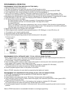
MOUNTING:
NOTE:
The images above and below are for illustration purposes only.
The GFO-1DL(F) wire terminals are directly on the unit, not in the chassis itself.
Operation plate (peel off
protective film). Bend at one
corner and remove, then
reattach after installation.
Loosen screw
(don’t remove)
Attach chassis to
wall surface, or
set on a desktop.
Cut appropriate sized
hole in wall, or install
BBX-1E during new
construction.