


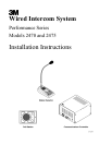

Performance Series
I/O Card and Noise Reduction Module
Installation
3
3M Model A125, Noise Reduction
Module, Installation (Optional)
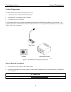
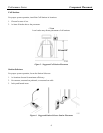
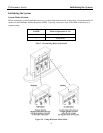
Figure 3. Noise Reduction Module
Installation
Be sure the system is powered off!. Refer to Figure 3.
The optional 3M™ A125 Noise Reduction board (3M part
number 78-9236-6453-2) improves the inbound intelligibility
of an intercom system by reducing environmental background
noise from vehicles, airplanes, noisy intersections, wind, etc.
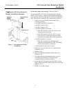
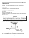
1. On the A125 circuit board, set the jumpers and
switches as follows:
• Set JMP1 and JMP2 to position A.
• Set SW1 number 1 ON
• Set SW1 number 2 ON
• Set SW1 number 3 as desired:
-- With SW1 number 3 OFF, the A125 is set for
restaurant noise reduction.
-- With SW1 number 3 ON, the A125 is set for
truck stop noise , which provides more noise
reduction with slightly more voice degradation.
• Set SW1 number 4 as desired:
-- With SW2 number 4 ON, the higher-end
frequencies are increased by 3 dB. This should
be set to the customer’s preference.
• SW1 numbers 5 and 6 are not used.
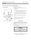
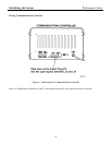
2. Remove 4 screws on each side of Communications
Controller cover.
3. Remove cover.
4. Plug Noise Reduction Module ribbon cable into
Connector J12.
5. Use upper and lower mounting brackets to secure
Noise Reduction Module to Communications
Controller chassis as shown in Figure 3.
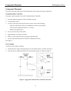
6. On the Model 2470 circuit board, Set JMP1 to open.
LED1 (adjacent to JMP1) blinks when noise reduction
module is active.
7. Replace cover and 8 screws.