


Performance Series
Wiring The System
7
Configuration Worksheets
Use Configuration Worksheets 1 through 3 (located at the end of this document) to plan and record your system
configuration. You can record the system wire locations, wire color scheme, and program settings on the
worksheets. Store the worksheets inside the cover of the Communications Controller.
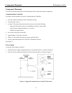
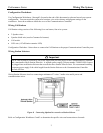
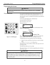
Wiring Call Stations
Call Station wiring consists of the following for a one-button, four-wire system:
• 2 Speaker wires.
• Speaker shield wire (used as Common for buttons).
• Call switch.
• LED wire. (if Call Station contains LED)
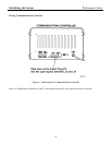
Configuration Worksheet 1 shows how to connect the Call Stations to the proper Communications Controller ports.
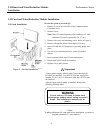
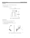
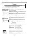
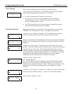
Wiring Station Selectors
!
Important
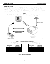
The D-2400 System is powered by one power supply that provides power for the Communications Controller
and a maximum of three Station Selectors. A separate power supply (3M part number 78-8095-0910-8) must
be plugged into each Station Selector that exceeds the three Station Selector limit. We recommend installing
a separate power supply if the cable length from the Station Selector to the Communications Controller
exceeds 100 feet.
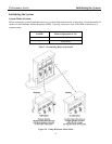
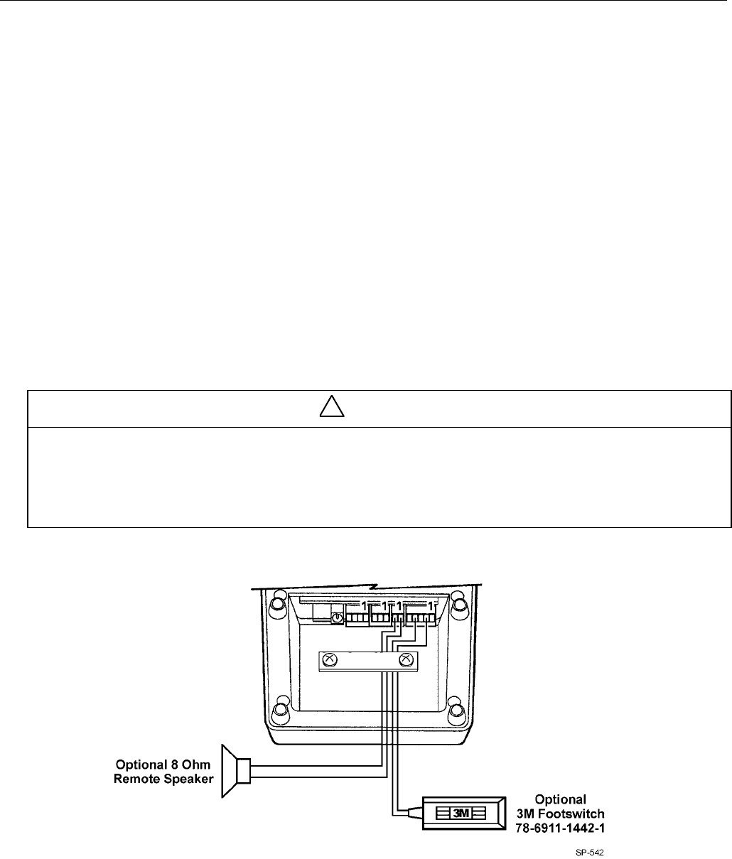
Wiring Station Selectors involves connecting a minimum of 7 wires: 3 audio wires and 4 power and
communications wires.
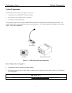
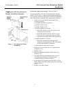
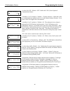
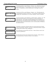
Figure 8. Connecting Optional Accessories to Station Selector
Refer to Configuration Worksheets 2 and 3 to determine the specific wires and connections to be made.