SUPER ABSORPTIONENVIRONMENTALLY FRIENDLY TECHNOLOGY
1. In order to prevent freeze-up of chilled water during unit shutdown,
the chilled water pump(s) and air handler must be run for 15 minutes
after the burner is shut off. This will allow time for the automatic dilu-
tion cycle to be completed.
2. The standard unit must not be subjected to water pressures in excess
of 981 kPa (10 kg/cm
2
G).
3. An expansion tank should be provided in the chilled/hot water line.
4. Thermometers and pressure gauges should be field-installed at the
inlet and outlet of the chilled/hot water line, and the cooling water
line.
5. During heating operation, the cooling water circuit should not be in
operation and should be blown down.
6. All external piping connections are provided with JIS 10K flanges un-
less noted.
7. A drain line must be installed from the smoke chamber drain to a floor
drain.
8. See Figure 32 (DE), Figure 48 (NE), Figure 61 (LE) for typical sys-
tem piping arrangement.
Field piping instruction
908070
60504030
200
109876543 20
100
01
02
03
11
12
13
21
14
22
23
24
31
32
41
42
51
52
53
Graph 17.
Hot water pressure drop curve (LE)
40
30
10
20
100
90
80
70
60
50
Pressure drop (kPa)
Flow rate (m
3
/h)
Installation and application data
Location and space requirements
The unit is designed for indoor application and must be located in a space
where the surrounding temperature of equipment is between 5°C and
45°C, and at no more than 90% relative humidity. Clearance must be
provided on either end to facilitate tube cleaning, or removal and clear-
ance on all other sides of the unit for general unit maintenance. See the
dimensional data tables for clearance requirements.
Water piping should be arranged so that the circulating pumps discharge
directly into the vessels. The water piping should be insulated to reduce
heat gain and to prevent condensation. Air vents should be located at all
high points in the water piping system, and drains should be located at all
low points to facilitate complete system drainage. To reduce vibration
and noise transmission, vibration absorbers should be provided. Shutoff
valves should be provided to allow unit isolation during maintenance.
Chilled water flow switch is provided on the unit and is preset to open at
approximately 50% of specified flow rate.
Water piping
D
B
C
A
Evaporator side
Absorber side
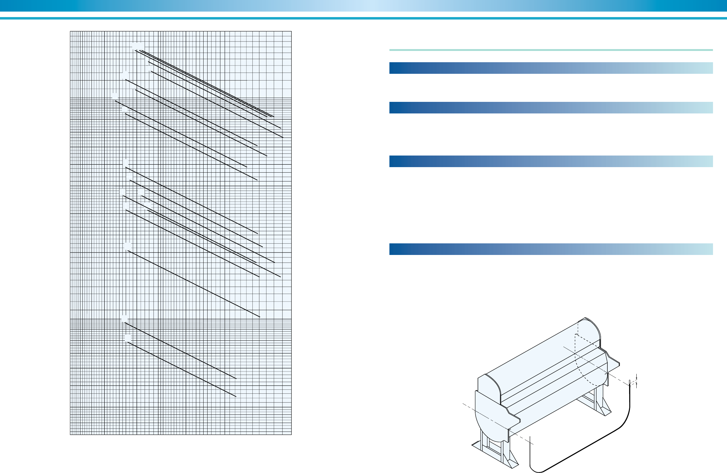
Strict leveling tolerances must be adhered to for trouble-free operation.
SANYO units are furnished with four leveling reference points, one on
each corner of the lower shell or tube sheet. Each reference point is
designated by three punch marks. A convenient method to check level-
ing tolerances is to fill a clear vinyl hose with water and measure the
difference in the water level at the two points. The tolerance that must be
maintained from end-to-end and side-to side is 1mm (1/25'') of difference
for each 1m length between points. It is not necessary to check levels
diagonally. When the unit does not meet this requirement, the unit must
be shimmed in order to meet leveling tolerances.
Leveling requirements
Figure 62. Leveling the chiller


