


=--~'~-'"
---,
)
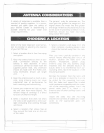
A variety of antennas is available from a
number of quality suppliers. It is recom-
mended you draw upon the advice of
your Marine Dealer in determining a
suitable antenna for your vessel and
range. requirements. '
The general rules for antennas are The
. i
more g~j/nthe greater the range and, the
higher above the water line the greater
the range. Antennas should be located so
as not to be in proximity to metal or'wets.
Antennas should not have excc~..::.ively
long coaxial feed cab/cs.
:: ~",.;.":'.~'..'..'':;o::C:H,
.
.
rlo
',"
N
'"':':':':,. :','::'~:U;~~;~L,:
.' ',' '" """",,
, ".-,'h ';,'::,/.;~;;:;~n.;:.:...
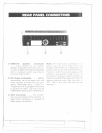
Someof the more important external fac-
tors to consider in selecting the location
of your MC790 are:
1. Select
a location that is free from spray
and splash.
2. Keep the battery leads as short as pos-
sible. Connection directly to the
battery is most desirable. If direct
connection cannot be made with the
supplied r power lead, any extension
should be made with # 10 AWG wire.
Long extensions should use larger
wire.
3. Keep the antenna lead as short as pos-
sible. Long antenna leclcJsCZlrlcause
substantial loss of performance for
both receiving and transmitting.
4. Locate your antenna as high as possi-
ble and clear from metal objects. The
reliable range of coverage is a direct
function of antenna height.
5.
Select a location that does not allow
the radio to be subjeCted to direct sun-
light (including that coming through
windows).
6. SeleCt a location that allows free air
flow around the heat sink on the rear
of the radio.
r
- ~
--
7. Select a location well away frorn the
ship's compass. Auxiliary speakers also
should be located away from the com-
pass,
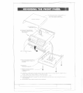
After you have cc!refl1l1y consicJerc(j the
various factors affecting your choice of
location, position the radio (wi(i! the
bracket, microphone, power iJlug,
antenna plug and any auxiliary plugs
installed) into the selected location to
assure, there is no interference with sur-
rounding items. Mark the location of the
mounting bracket.
Remby~ ,the bracket fror:n the racJio and
use itas a template to mark the hole') to
be drilled for the mounting rlc!rc!wcIre.
Drill the holes and mount the br,]cket
with hardware compatible with the mate-
rial of the mounting ~urface. fnst;l:1 the
power cable (red f~ +, black 1\ -I,
antenna and all other auxiliarycables and
accessories.
Install the radio into the mounting
bracket and connect all cables an(j (~cces-
sories to the apprf)priate jacks and
connecrors.
-
----
[--
--