8
Mounting Configurations
The EMS-4001 mounts in a standard 19 inch equipment rack and is 1 rack unit high. Install the two supplied rack
mount cosmetic covers when installing the EMS-4001 in the rack.
When rack mounting components, you may not be able to access the sidetone trimmers after the components have
been mounted. In this case, you can position the components in the rack and make all required connections. Then
adjust the sidetone trimmers before installing and tightening all rack mount screws.
Connection Notes
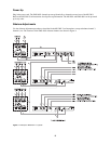
Typical connections for the MS-2001/EMS-4001 are shown in Figure 3.
Cables
The numbers below correspond to the cable numbers in the connection drawing in Figure 3.
1. Single channel intercom cable. Sold separately. Use Telex “ME” cables, below, or can also be built by using two
twisted pairs in a shielded cable: Pair 1 in used for pins 2 and 3. Pair 2 has both wires connected to pin 1.
ME-25: 25’ (7.6 m) cable with male and female 3-pin XLR connectors.
ME-50: 50’ (15.2 m) cable with male and female 3-pin XLR connectors.
ME-100: 100’ (30.4 m) cable with male and female 3-pin XLR connectors.
2. Shielded patch cable, 9-pin Male D-sub to 9-pin Female D-sub. Customer local purchase: available at Radio
Shack, etc. Note: All pins must be connected straight through (i.e. pin 1 to pin 1, pin 2 to pin 2, etc...).
3. Shielded patch cable, stereo miniplug to stereo miniplug. Customer local purchase. Available at Radio Shack,
etc...
4. 18” (457 mm) EXP IN/OUT cable, stereo miniplug to stereo miniplug. One supplied with each EMS-4001.
5. Shielded audio cable. Must have male 3-pin XLR connector at one end for connection to the XP-USPG or XP-
4PGM program inputs. Pin-out for program inputs is as follows:
Pin 1: common
Pin 2: + program input
Pin 3: - program input
6. Shielded audio cable. Must have male 3-pin XLR connector at one end for connection to the XP-USPG PA
output. Pin-out for PA output is as follows:
Pin 1: common
Pin 2: + PA output
Pin 3: - PA output
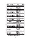
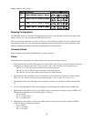
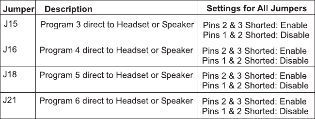
Table 2 - EMS-4001 jumper settings.


