


5
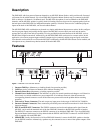
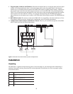
9. Program Inputs Connector and Trimmers: Each intercom channel has its own program input and level adjust
trimmer. For each program input, there is an internal jumper which routes the program either to the intercom
channel only, or to both the intercom channel and the MS-2001 headset or speaker (default setting). Additionally,
the program signal to the intercom channel may be turned on or off via the MS-2001 front panel programming.
There is also an internal program interrupt DIP switch which selects either automatic program interrupt when the
station operator activates a channel’s talk key, or no program interrupt during talk. The EMS-4001 program
input connectors may be broken out to common 3-pin XLR audio cables using the optional XP-4PGM Breakout
Panel.
10. BAL/UNBAL switch: This selector switch sets the EMS-4001 for compatibility with either Audiocom or Clear-
Com channel connector pin-outs, channel power requirements, and call signaling requirements.
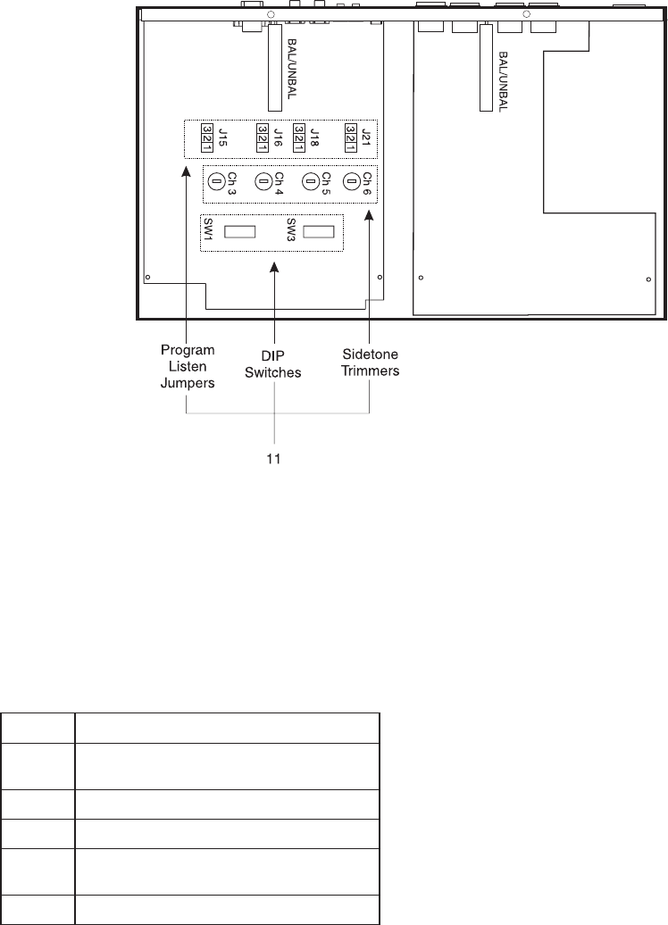
11. Configuration switches, Jumpers and Sidetone Controls: These let you customize the operation of the EMS-
4001 to match your intercom system requirements.
Figure 2 - EMS-4001 internal DIP switches, jumpers and adjustments.
Installation
Unpacking
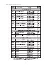
The EMS-4001 is supplied with the following items. Contact the shipper or your Audiocom dealer immediately if
anything is damaged or missing. Detach and fill out the registration card and return it to Telex to properly register
your intercom station.
ytitnauQytitnauQ
ytitnauQ
ytitnauQytitnauQnoitpircseDnoitpircseD
noitpircseD
noitpircseDnoitpircseD
1
rewoPdnanoitatSretsaMnoisnapxE1004-SME
ylppuS
1dracnoitartsigerdnaytnarraW
1snoitcurtsnIresU
1
enohp)mm5.3(hcni-8/1htiw,elbacTUO/NIPXE
sgulp
2srevoccitemsoctnuomkcaR