


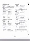

2.1
Power
Rquhm&,
Type
Of
System,
Pow-
Method
And
Power
Supply(i)
Power Ranuremnts
To
maintain
a bridging
10,000 ohm0
bpedanw
to
the
intenmu
line,
the
CM300/RM300
requires
+18
to
+35
volts
DC.
To
opemte
in
Id
power
or
tathy
modes,
the
CM300/RM300
rsguires
from
+
15
to
+35 volts
DC,
but
ic
opesable
at
reduced
performauce
from +12
to
+17.9
volts.
~CMHKllRM300cmbe~edina(l)three~
system,
(2)
two
wirs
system,
or
(3)
speciPl*
win
sy--
NW:
Opemdion
of
a
aydm
or
maximum
load
dOCS
not
allow
for
other
miations
such
as
fempermun,
line
*e,
able
re-,
and
suw.
A
nwrt
pnrdcni
oppmoah&&opc~~sy~~nononflrnn80%
of
-Pad*.
In
(3) above,
a
ld power supply
provides
12 to 24 volts
DC
at
120
mill*mpms
peak
for
esch
station,
or, for
nmote
single
station
operation,
two
9-volt batteries
in
mliesrmy
be&.
In
(1)
&
(3)
above,
the
two
Wireb
curyiug
audio
require
one
system
tamhation
wnsisting
of
a
UX)
ohm
mistor
mula
100
mimfarad
capacitor
in
series.
This
combination
is~rrossthetwowircs.
Coanectpolorized
@tors
negative
to
system
circuit common.
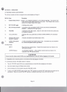
To
Wl
tbe
0%300IRM300:
PWCMR
M@@
1.
~thetypeofsysteminwhichtbe
CM300/RM300
is
to
be
htalled.
Detemine
the
pow-
Powerismrri~tothe\mitfromasystem~supply
*~dpo~ersllppl~(i~).
using
three
diffcrrnt
methods:
2.
Dstamine
the
mwnting
of
the
C!M300/RM300.
(1)
In
a
3-6
system
('Series 17" type),
the
power
is
Stpuatefromtheaudiodsuppliedcmtnlly.
3.
Read
'Choosing
Hadsets
or
Ehds&s'.
(3)
Ina~twowirsSystem(LoulPowo),esch
cM300~300
is
ldy
pawerrd
md
opmtes
on
switch
ChnneJ
two.
Ths
cM300/RM300s
are
in- using
two
win
able.
Porn
is
suppliedbyabatteryoraloulpowgsupply.
The
local
pow
supply
should
be
isolated
from
eutb
ground.
In
(1) above,
the
power supply
is
a
regulated
supply,
24
volts
DC
to
32 volts
DC,
1.5
.mperes.
This
supply
cm
opuw
up
to 50 CM300/RM300
and
30
CM300LIRM300L
user
strtiws.
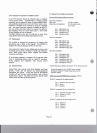
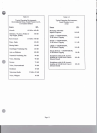
For
case
(2) above,
rsgtming
cutmats
shown,
the
supplies
versus
rmximum
rmmber
of
Etatiom
pmvered
are:
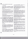
power Smly
!xx!!2
phl300 (37mA)
!xaL
RM300L
(60n1,Q
Model PS8 (0.43A) 11
Model
PSI5 (1.OA) 27
Model
PS31(1.5A) 41
4.
Dcraminc
the
cabling
mpkmata.
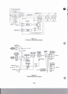
5.
Create
a
system
block diagram
&
equipment
Si
(if not
Wy
available),
them
iustalI
the
systua
6.
Verify
wmct
rystem
opention by
using
the
checkout
procedure
in
this
dvpter
(2.6).
7.
Update
the
systeal
block
diagm,
squipment
list
and
my
0th
-on
to
reflect
the
'as
hitdled'
dguration.
If
the
system
block
diagram
was
origi~Uy
d
by RTS Systems,
swxi
a
copy of
the
'as
instrlled'
system
block
diagnm
to RTS Systems.
This
diagram
will
be
ussd
to
update
the
original
docummtoton.
d
for
fuhue
service
~ppt.
Page
7
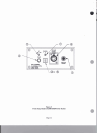
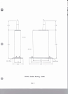
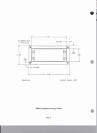
?hs
a300
mom&
in a
console,
use
the
installation
diagram
at
the
back
of
this
maoual
for cutout
diiiws
md ding
hole Id-. The RM300 mounts
in
an
EIA
19
inch
rack.