


1.1
DESCRIPTION
The Model CM3W
is
a console mount, twhl
intercom
user
station.
The
Model
RMUX)
is
a
rack
mnmt,
two-chmd
intmom
user
station. The
user
station
is
designed
to
he
used
in a
full
duplex, wafermce
line
intercom
system.
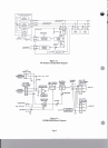
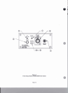
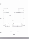
Confereuce
Line
IntMcom
Svstem (Figure
1-1)
A
conf-
line
intercom
sysIem
allows a
group
of
people to
talk
and
listrn
on
a single chaaael.
On
this
c~,allusersanlistrnwhe~anreormmotbsr
users
are
talking (eonf&g). Up to 75
usns
csn
share
the
same
dermc8
line
(or
confcrma
bus).
Full
duplex
@on
allows
two
way conversation
at
the~time,thatis,oneuser~~tassond
The
CM3W/RM3W, with
a
hedset,
intcrhces
a
hurmn
usertotheinintaoomsystem.
Tbeusertdksandlirtms
using
the
head& (or a
hmdsst).
The
headset
umnects
to
umnector (optbdly five or
six
pin).
The
CM3W/RM3W
uneeds
to
the
systsm
using
a
the
conductor
"mi-
type
cable.
me
CM3w/RM3w
wataiU6
four
~011tmIs:
the
volum anmoll,
the
latching
microphone
switch,
the
momntary
microphone switch,
md
the
chanael
select switch.
On
the
Model CM3W/RM300L,
the
momentary
microphone switch
is
replaced
with
the all
tight
button.
Volume Control
The
volum wntrol on the CM3WlRM3W
has
a wide
range to
canpensote
for:
user
he&$
differences,
ambi-
ent noise variation, variations in
headse4
I
haadset
d-
tivity.
and
variations in voice. The volume watrol in
the
CM3W/RM3W
mhtcea
distortion by driving the
headphone amplifier
oaly
as
much
as
needed.
In
nod system opention, one
a
nrole
users
talk
and the
othm
listen.
A
microphone switch on each station allows
the talker's microphone to
he
mabled
and
allows
the
listmas to
keep
their microphones disabled.
In
this
condition,
speech
intelligibility is
euhanced
since
backgmund
noise from other microphones is not present.
On
the
Model
CM300/Rhi3w, a
latching
switch or
momentary
push
button
tums
the microphone on.
The
mommtary
push
hutton
allows
quick
bursts
of
communication, especially
useful
in
a
high
noise mvi-
ronmmt.
Ihe
latched
position allows
'hpnds
fne'
op
don,
when
the
llscr
aeuls
to have two way conversation
while
paformiDg
anok activity.
The Channel
Select
Switch
A
chmnel
sdector
switch allows a choice of two
(optionally
three)
ch.nnels.
Whm
the
switch is
on
the
'I'
positionthestationtalksandlistensonchnollcl1,onthe
"2'
position, channel
2,
and
m
on.
On
larger
systems
the
'1'
position may
be
any
system
channel
(1
through
12
for
example). Similarly, for position
"2'.
See
Section
2.1
for
DC
powering
rsqoinmeats
under
these conditions.
Call
Li&
Push
Buttog
(CM3WL/RM3WL, only)
Pushing
this
button
transmits
a
mll
signal
to all other
units
on
the
chmnel
selected
by
the
cbl
selector
switch.
A
all
signal
on
this
&amel
will
cause
the
all
light
push
buttontotlash.
~&pshrateis2to5timDsapecomd.
The
all
signal
itaclf
is
a
20
kilohertz
signal.
The
CM3MYRMUK)
.ad
CM3WLRM3WL
use
the CC33
card
ere#
u
idhated
bclow.
Codcl
at
the
cad
of
each
pngnph
iadiatc
thc
cud
d.
Codcl
ue:
*CC33
urd,
**CW
card.
MCC(5
cud.
(CC33
sehemtic
i
SD1464,
CCWCC45
.ohcrmtic
is
SD1427).
-DL:
Dual
Littcn
on
two
channclr.
The volume wntml
is
~toadual~tricpotcntiomctawithtwoknohs.
The
0h.nnclrelcctmachmutatheWLugunl.
Thcouuidekmb
folh
thc
duancl
selector.
The
Mi
knob
i
the
non-talk,
listm
only
0b.naCl.
-E:
Rognm
Inp,
w.
Dch
line loop(hrough,
the
hkncedpmgrunufedmmatud.
Pinr2Md3uethcinput
wnncUionr.
A
dual
W&
ptentiomcta
with
two
knobs
pmvidu
rcp.ntc
level
controls
for
intercom
md
pmgnm.
-3CII:
The
Ciimd opmtion. Line
and
LoopUvough
connecton
ue
changed
to
4-pin
fmm 3-pin.
A
3-position
dunnd
seka
mach
rcpkes
ihc
2-position
witch.
-USMB:
UnSwitched
Micmphonc output,
Balanced.
Deldeo
linc
boplhrough.
Led
-7dBm
to
+3dBm.
.
Thc
USMB
pmvidu
I
linc
level microphone signal
to
other systems
such
u
m
lntenupted
Feuihack
System
(IFB),
telephone,
radiotelephone.
or
Stage
Announa.
-LP:
Loul
Paver
munu.
A
small
moduk
wnvem AC line
power
to
low
voltage
to
power the
urer
station.
a
.cparatc
connector
is
provided. The
unit
docs
not
use
power Cmm
the
intercom line.
Page
5