


11
6
7. INTERCOM CHANNEL CONNECTORS: On the BP-2002, intercom channels are
connected via a pair of 6-pin connectors (one male and one female). The male
and female connectors are wired together in parallel, providing a “loop through”
at each connector pin. Use one connector to connect to the intercom
channel. Use the other connector to “daisy chain” a cable to the next beltpack
or other station on the channel.
Local Power Input
Normally the BP-2002 is powered from the intercom system and will turn on
with the intercom system. The BP-2002 beltpack may also be powered from
an optional power supply (21-30 VDC) connected between pin 2 (+) and pin
1 (-) of the intercom channel connector.
8. INTERCOM CHANNEL CONNECTORS: On the BP-1002, the intercom channel is
connected via a pair of 3-pin connectors (one male and one female). The male
and female connectors are wired together in parallel, providing a “loop through”
at each connector pin. Use one connector to connect to the intercom channel.
Use the other connector to “daisy chain” a cable to the next belt pack or other
station on the channel.
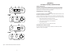
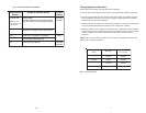
OPERATING MODES
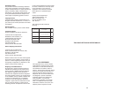
The microprocessor within the BP-1002/BP-2002 controls four modes of
operation that affect the Microphone Kill and Audible Call Alert features. These
modes can be seen in Table 1.
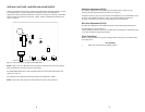
CONNECTOR PIN CONFIGURATIONS
Headset Connector
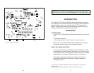
Type: XLR-4M (callout 6 in Figure 1)
Pin 1 Headset microphone low
Pin 2 Headset microphone high
Pin 3 Headphone high
Pin 4 Headphone low
Intercom Channel Connectors
BP-1002
Type: One XLR-3M and XLR-3F pair (callout 8 in Figure 1)
Audiocom
®
Mode (Internal switch SW1 set to BAL position)
Pin 1 Common
Pin 2 Intercom audio/call low and +24 VDC input
Pin 3 Intercom audio/call high and +24 VDC input
Clear-Com Mode (Internal switch SW1 set to UNBAL position)
Pin 1 Common
Pin 2 +30 VDC input
Pin 3 Intercom audio/call signal
BP-2002
Type: One XLR-6M and XLR-6F pair (callout 7 in Figure 1)
Audiocom
®
Mode (Internal switch SW1 set to BAL position)
Pin 1 Common
Pin 2 Local power (21-30 VDC)
Pin 3 Channel A intercom audio/call low and +24 VDC input
Pin 4 Channel A intercom audio/call high and +24 VDC input
Pin 5 Channel B intercom audio/call low and +24 VDC input
Pin 6 Channel B intercom audio/call high and +24 VDC input
Clear-Com Mode (Internal switch SW1 set to UNBAL position)
Pin 1 Common
Pin 2 Local power (21 to 30 VDC)
Pin 3 Channel A +30 VDC input
Pin 4 Channel A intercom audio/call signal
Pin 5 Channel B +30 VDC input
Pin 6 Channel B intercom audio/call signal