


5. SYSTEM CONNECTOR INTERFACE
42
LZT 123 7589 R1A
The electrical characteristics are given below. The signal reference is
DGND.
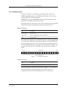
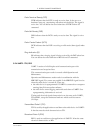
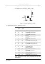
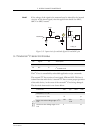
5.12 Buzzer
Connecting the BUZZER signal to an inverting transistor-buffer followed
by a piezoelectric transducer enables the radio device to play pre-
programmed melodies or sounds.
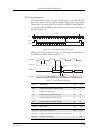
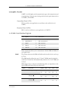
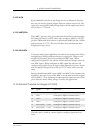
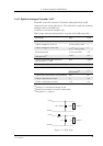
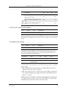
5.13 LED
The LED states shown below, are hard coded.
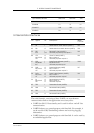
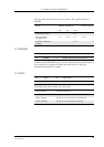
Mode SERVICE Voltage (V) Drive Capacity
Min. Typ. Max.
Normal Operation 0.8 -
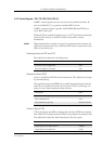
Service/enable
programming
1.9 2.75V 3.6 > 1 mA
Absolute maximum
voltage
13.5
Pin Signal Dir Description
31 BUZZER O Buzzer output from radio device
Pin Signal Dir Description
33 LED O LED Output from radio device
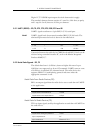
LED indication Operational status
No indication No power or in the OFF state
Green, steady Power on, not connected to a network
Green, blinking Power on, connected to a network