


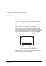

5. SYSTEM CONNECTOR INTERFACE
22
LZT 123 7589 R1A
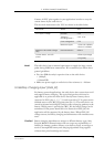
5.2 General Electrical and Logical Characteristics
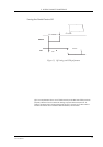
Many of the signals, as indicated in the table above, are high-speed CMOS
logic inputs or outputs powered from a 2.75 V ± 5 % internal voltage
regulator, and are defined as Digital 2.75 V. Whenever a signal is defined
as Digital 2.75 V, the following electrical characteristics apply.
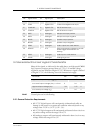
1RWH Unused pins can be left floating.
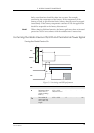
5.2.1 General Protection Requirements
• All 2.75 V digital inputs will continuously withstand and suffer no
damage in the power-on or power-off condition when subjected to any
voltage from - 0.5 V to 3.47 V (3.3 V + 5 %).
• All 2.75 V digital outputs will continuously withstand a short circuit to
any other voltage within the range 0 V to 3 V.
• All analogue outputs will continuously withstand a short circuit to any
voltage within the range 0 V to 3 V.
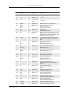
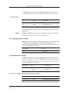
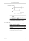
49 PCMO O Digital 2.75V Codec PCM digital audio output
50 PCMI I Digital 2.75V Codec PCM digital audio input
51 PCMSYNC O Digital 2.75V DSP PCM frame sync
52 PCMCLK O Digital 2.75V DSP PCM clock output
53 MICP I Analogue Microphone Input positive
54 MICN I Analogue Microphone Input negative
55 BEARP O Analogue Speaker output positive
56 BEARN O Analogue Speaker output negative
57 AFMS O Analogue Audio output from radio device
58 SERVICE I 2.7V Flash programming voltage for the MS.
Enable logger information if not
flashing.
59 ATMS I Analogue Audio input to radio device
60 AGND - Analogue Analogue ground
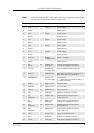
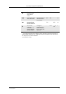
Pin Signal Name Dir Signal Type Description
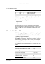
Parameter Min. Max. Units
High Level Output Voltage (V
OH
), I
o
= –2mA 2.2 2.75 V
Low Level Output Voltage (V
OL
), I
o
= 2mA 0 0.6 V
High Level Input Voltage (V
IH
) 1.93 2.75 V
Low Level Input voltage (V
IL
)00.5V