


Guardian Telecom Inc.
Installation and Operation
Page/Talk Indoor Housing
Page 7
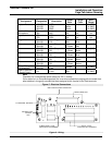
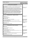
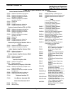
Assignment Designation Description
Jacket
Color
Stripe
Color
Wire
Gauge
System Power J4A/J5A HOT Black 14 AWG
J4A/J5A COM White 14 AWG
J4A/J5A GND Green 14 AWG
Ambient Noise J6A MIC + n/a n/a n/a
Microphone J6A MIC - n/a n/a n/a
Speaker J7A SPK + n/a n/a n/a
J7A SPK - n/a n/a n/a
Page Line J2A/J3A PA Page Line Blue Red 18 AWG
J2A/J3A PB " Red Blue "
Channel J2A/J3A 1A Channel 1 Red 18 AWG
J2A/J3A 1B " L. Brown Red "
J2A/J3A 2A Channel 2 Violet 18 AWG
J2A/J3A 2B " L. Brown Violet "
J2A/J3A 3A Channel 3 Blue
18 AWG
J2A/J3A 3B " L. Brown Blue "
J2A/J3A 4A Channel 4 Brown 18 AWG
J2A/J3A 4B " L. Brown Brown "
J2A/J3A 5A Channel 5 Yellow 18 AWG
J2A/J3A 5B " L. Brown Yellow "
Group Muting of J2A/J3A Mute
Loudspeakers J2A/J3A Park
Orange
18 AWG
Spare Conductor
(Special Order)
n/a Extra Red 12 AWG
Note:
Channels 2 to 5 connections remain empty for ExP-1 hookup.
If this station is in a Group Muting series, but is not to be muted when paging calls are made from
other stations in the group, connect the wires assigned to this function to the Park terminals.
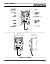
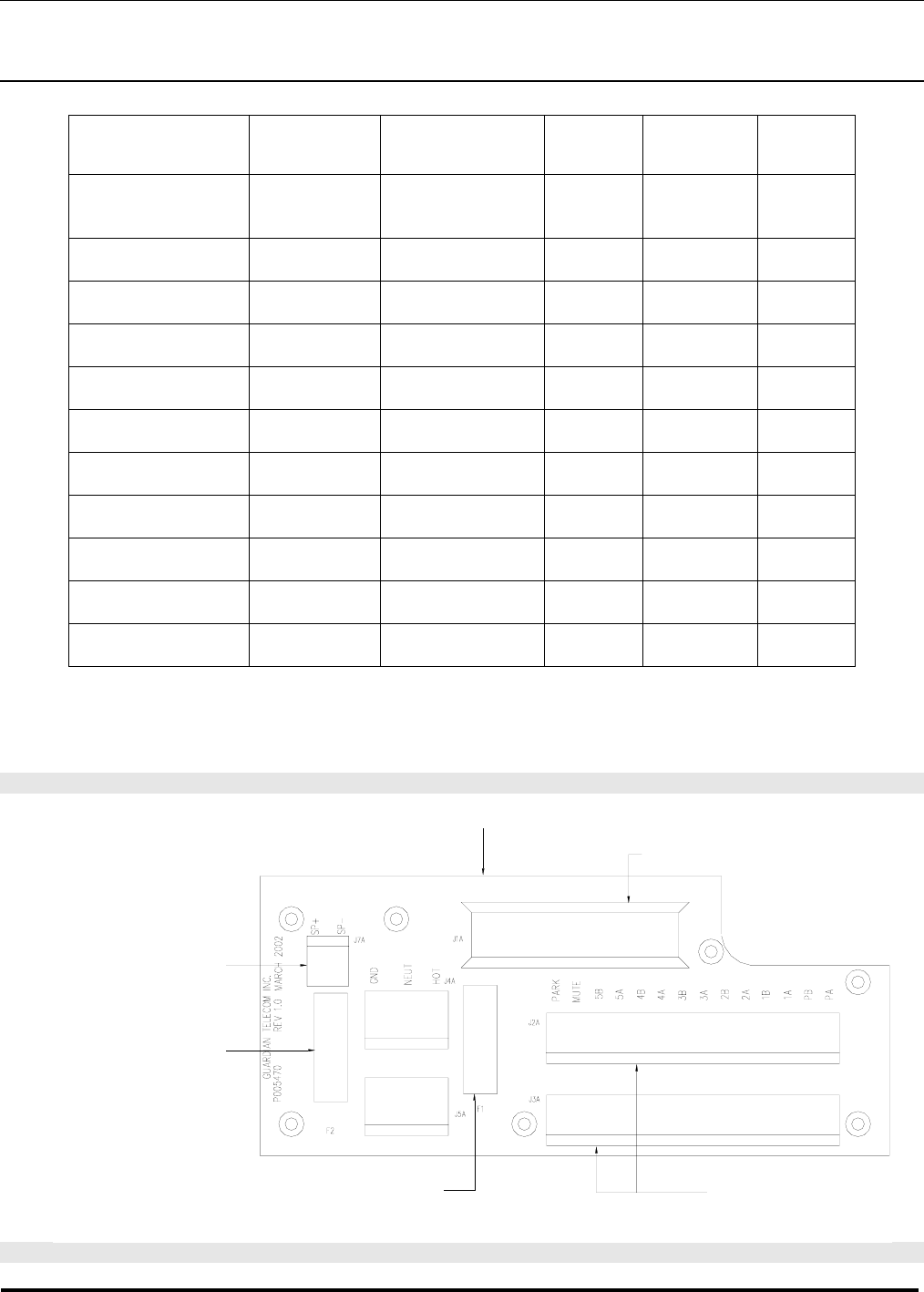
Figure 5 - Electrical Connections
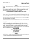
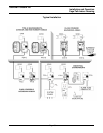
Figure 6 - Wiring
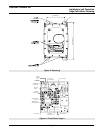
MAIN CIRCUIT BOARD CONNECTOR
SPEAKER FUSE
0.5A/250V
GDA
MAIN CONNECTOR
POWER SUPPLY FUSE
(SEE SPECIFICATIONS)
J7A EXTERNAL SPEAKER
J2A/J3A IN/OUT
PAGE AND TALK CHANNELS