


Guardian Telecom Inc.
Installation and Operation
Page/Talk Indoor Housing
Page 6
Installing the ExP-1/-5
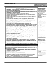
WARNING - high voltages are present in this equipment when it is
connected to the power source.
• Ensure that the location is non-hazardous before proceeding with any
installation or electrical wiring.
Caution: Installation or
electrical wiring in a
hazardous location
could result in serious
injury to personnel or
damage to property.
• Ensure that the station is set up for the correct voltage.
• Follow all appropriate electrical codes and use only approved electrical
fittings for the installation.
Tip: check the
identification label on the
faceplate.
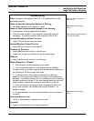
• Choose a wall location that is free of obstructions and permits space for
conduit or wire.
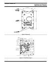
See:Figure 2 - ExP-1/-5
Dimensions
• Ensure mounting can support 30 lbs./14 kg and any additional load.
• Use the template provided to locate and drill holes for mounting screws.
• Remove the bolts on the faceplate and remove the faceplate.
• Secure the unit to the wall.
• Ensure that none of the electrical connection circuits are live.
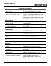
• Bring cable(s) into the enclosure through the conduit entrance(s) and attach
individual wires to the Combicon connector(s). Attach the wires from the
first or only cable to the bottom connector. Make Talk channel connections
to terminals 1A and 1B for the single line ExP-1. Plug any unused cable
entrances.
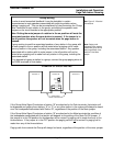
Note: Be careful when
removing the faceplate.
The circuit board is on
the faceplate.
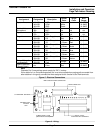
See: Figure 4 - and
Figure 5 - Electrical
Connections
• If the station is part of a Group Muting series connect the wires assigned to
this function to either the Mute or Park terminal on the connector.
• Set the speaker mute jumper on the circuit board to the desired position.
See: Group Muting
• Plug the connector(s) into the receptacle(s) on the interface board.
• Ensure all connections are secure.
• Apply a bead of lubricant to the machined surface of the housing.
• Replace the faceplate ensuring that the connector is properly seated.
• Torque faceplate bolts to 13.5 ft. lbs. (18 Newton-Meters).
• Apply power to the system.
Tip: The lubricant acts
as a seal to prevent
water and dust from
entering the enclosure.
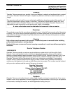
• Wait at least 20 seconds then check the speaker volume by making a
paging call. If alteration to the speaker volume is necessary, remove the
faceplate and adjust the speaker level potentiometer on the circuit board –
clockwise rotation increases the volume.
• Test the installation by making a call as described in the operating section.
Note: Adjust speaker
volume while ambient
noise at the station is at
a minimum.
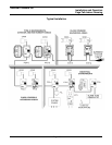
See: Figure 6 - Wiring
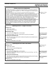
Accessing the Interior of the ExP-1/-5
Follow these instructions when necessary to access the interior of the ExP-1/-5
for adjustments or repairs.
• Declassify the hazardous area or remove power before proceeding.
• Remove the faceplate cover bolts.
• Lift off the faceplate cover.
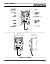
See: Figure 1 - ExP-1/-5
Features
• Perform the necessary adjustments or repairs.
• Replace the faceplate and bolts ensuring that the connector is properly
seated. Torque faceplate bolts to 13.5 ft. lbs. (18 Newton-Meters).
• Apply power to the wall station and test by making a call.
Note: Be careful when
removing the faceplate.
The circuit board is on
the faceplate.