


Page 27
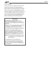
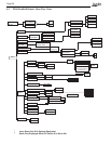
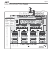
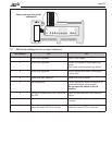
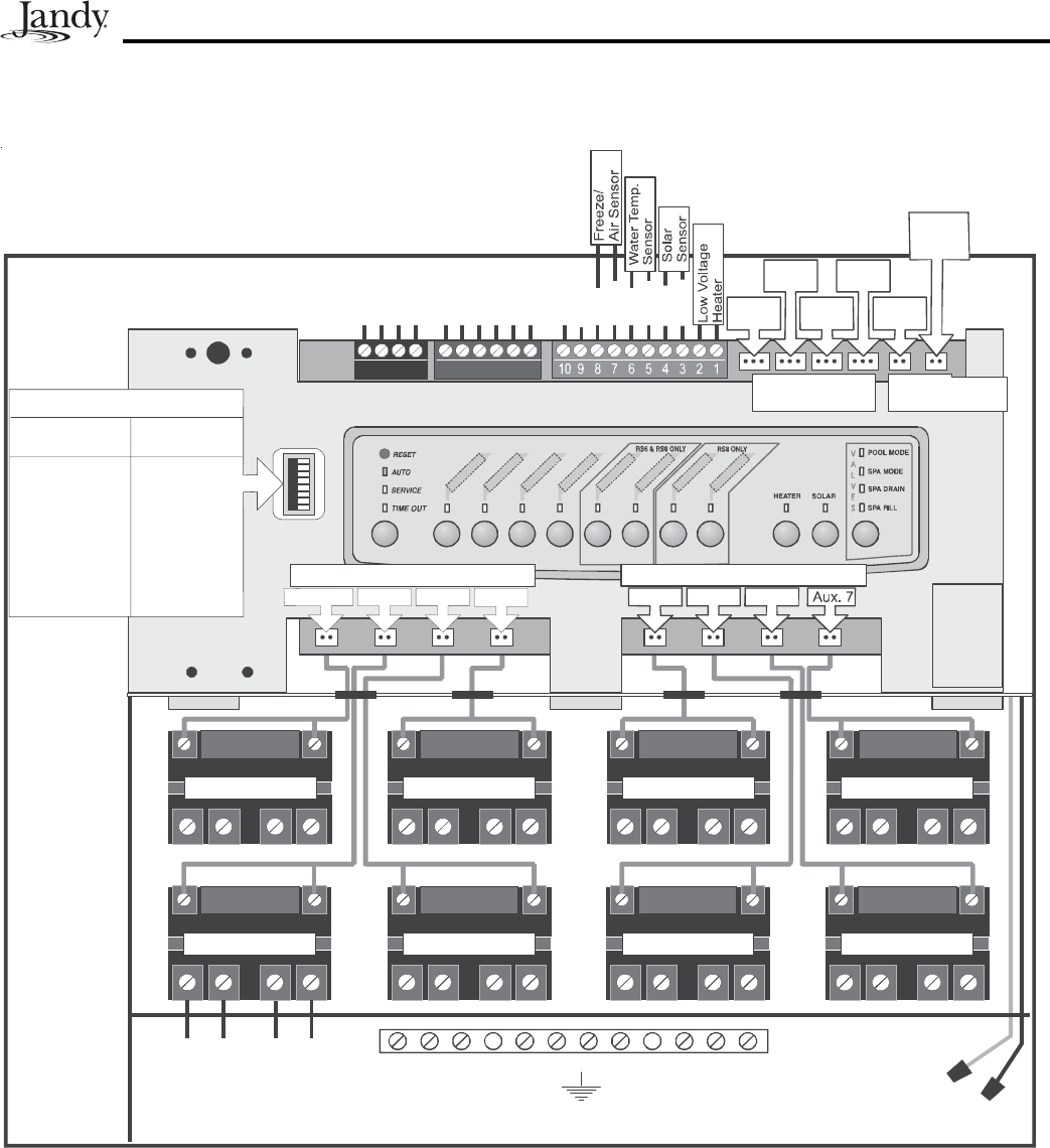
Section 6. Power Center Wiring Diagram
Aux. 4 Relay
Aux. 7Relay
Aux. 5 Relay Aux. 6Relay
Filter Pump R elay
Aux. 3 Relay
Aux. 1 Relay
Line One
Low Voltage Raceway (do not run high voltage wire in this compartment)
Line Tw o
Load One
Load T wo
Aux. 2Relay
Grounding Bar
Wire Nut to
120VAC Power
System P ower
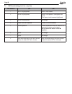
Intake
JV A
Cleaner
JVA
Solar
Pump
Ret urn
JVA
Solar
JV A
Elect.
Heater
Red
Black
Green
White
Yellow
Green
Black
Red
Brown
To Remote
(brownterminalbar)
ToSensors,etc.
(green terminalbar)
To Controller
(redterminal bar)
4321 654321
Blue
Red
Black
Red
Black
F. Pump
Aux. 2 Au x. 3
Aux. 6Aux. 5Aux. 4
Relay Sockets
(24VDCoutput)
JVASockets
(24 VAC output)
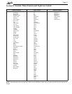
#OFF
1Aux1
21SPDPump
3Aux3
4 Cool Down
5Normal
6 S pare A ux
(Pool Mode)
7 See Manual
8 Heater 3 min.
Off
Battery
(9Volt)
Dip Switch Settings
Factory Se tting
ON
Cleaner
2SPDPump
Spa Spillover
Disabled
See Manual
S pareAux
(SpaMode)
See Manual
Red
Black
Not Used
Not Used
F
I
L
TE
R
P
U
MP
A
U
X
1
A
U
X
2
A
U
X
3
A
U
X
4
A
UX
5
A
U
X
6
A
U
X
7
Relay Sockets (24 VDC output) Relay Sockets (24 VDC output)
When T urned
Heater 5 min.
Off
Aux 1.