


Page 16
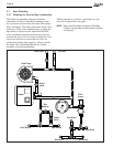
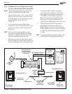
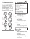
3.4.4 Guidelines for a Gas Heater and a Jandy
AE Series Heat Pump/Chiller Installation
NOTE The following steps provide the procedure for
installing a Jandy AE Series Heat Pump.
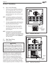
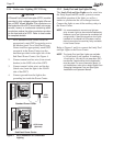
1. Install a fi xed resistor, with a value of 2.2K
Ohms, in the solar sensor terminals #3 and
#4 of the green, 10-pin terminal bar of the
AquaLink RS Power Center (see
Figure 16).
2. To run the wires from the Heat Pump,
remove the 5 screws that attach the service/
wiring cover panel to the heat pump (see
Figure 16).
NOTE One end of the wiring reserved to run into
the conduit connection labeled “Low Voltage
Connection”, located on the lower right hand
side of the heat pump (see Figure 16).
3. Run the wires from the Heat Pump control
panel through the wiring conduit located on
the outer right hand side of the Heat Pump.
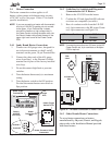
4. Connect the Heat Pump to a standard
relay, then connect the relay to the solar
pump output on the PCB. Set the time to
11:59 PM; at 12:00 AM, the AquaLink
RS will auto-relabel Solar as Heat Pump.
Otherwise, the AquaLink RS will auto-
relabel Solar as Heat Pump within 24 hours.
5. The Solar Button will activate the heat
pump/chiller and the Pool and/or Spa
Heater Buttons will activate the gas heater.
In this manner the pool or spa can be heated
or chilled by the heat pump, the gas heater
or both.
NOTE To program the Heat Pump control panel, refer
to the Jandy AE Series Heat Pump Manual.
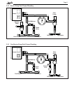
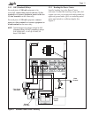
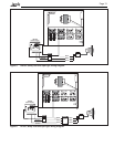
Figure 16. Heater and Heat Pump/Chiller Wiring
4321 654321
10987654321
Battery
(9Volt)
Gas Heater
Heat Pump/Chiller #2
Service/Wiring
Cover Panel
Fireman's
Switch
From Fusible
Link
To Pressure
Switch
Port for Low
Voltage Wires
Standard
High
Voltage
Relay
Heat Pump/Chiller #1
Gas Heater Connections
Terminals 1 and 2
2.2K Ohms Resistor
in Solar Sensor
Terminals for Heat
Pump/Chiller
Low Voltage
Wiring to Low
Voltage Port
on Heat Pump
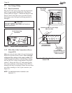
Service/Wiring
Cover Panel
Port for Low
Voltage Wires
PDA
Transceiver
J-box
To Heat Pump #1
To Heat Pump #2