


16 CIRCUIT OPERATION
16.1. Outline
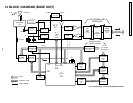
Base unit consists of the following ICs as shown in BLOCK DIAGRAM.
• • CPU:IC2
− − Controlling the whole system
− − Forming/analyzing all data signals (ACK, CMD signal etc.*)
− − All interfaces (ex: LED, KEY, SP, Mic, LCD, Detector Circuit (Charge/ Power Down)
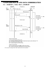
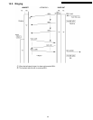
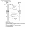
*Refer to EXPLANATION OF CPU DATA COMMUNICATION (P.32).
• • RF IC:IC1
− − PLL Oscillator
− − Detection
− − Compress/ Expander
− − first/ second mixer
− − Amplifier for transmission and reception
• • Additionally,
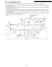
− − Power Supply Circuit
− − Reset Circuit
− − Charge Circuit
− − Telephone Line Interface Circuit
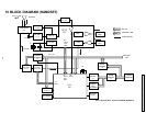
Handset consist of the following ICs as shown in BLOCK DIAGRAM.
• • CPU: IC2
− − All data signals (forming/analyzing ACK or CMD signal*)
− − All interfaces (ex; LED, Key, Buzzer, Detector Circuit, Charge, Battery Low)
− − RAM for keeping the data (CH Number, ID Code, etc.)
• • RF IC:IC1
− − PLL Oscillator
− − Detector
− − Compress/Expander
− − first, second mixer
− − Amplifier for transmission and reception
*Refer to EXPLANATION OF CPU DATA COMMUNICATION (P.32).
38
KX-TC1205RUB / KX-TC1205RUW / KX-TC1205RUS / KX-TC1205RUF