


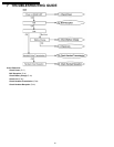
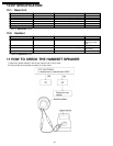
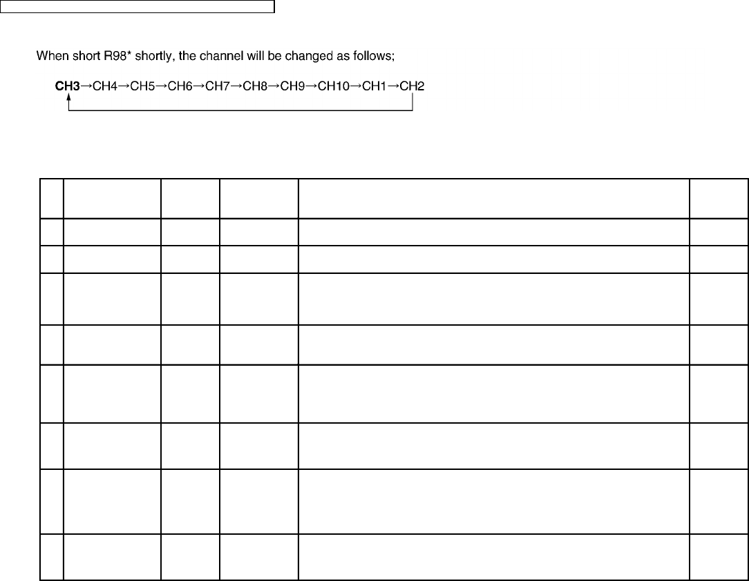
8.2. How to change the channel
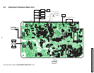
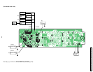
*: Refer to Flow Solder Side View (P.66).
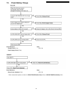
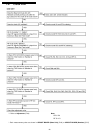
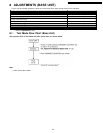
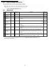
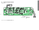
8.3. Adjustment
Adjustment Items Test Mode Adjustment
Point
*Procedure Check or
Replace
Parts
(A) RX VCO
Confirmation
3ch Talk -
• • Confirm so that the reading of the Digital Voltmeter is 1.5V ± 0.5V.
IC1, L10,
C26
(B) TX VCO
Adjustment
3ch Talk T6
• • Adjust T6 so that the reading of the Digital Voltmeter is 2.0V ± 0.1V.
IC1, DV1,
T6
(C) TX Frequency
Adjustment
3ch Talk VC1
• • Adjust VC1 so that the reading of the frequency counter is 30.175MHz ±
0.1KHz.
IC1, X1,
T6,
DV1, C35,
C40, VC1
(D) TX Power
Adjustment
3ch Talk T5
• • Adjust T5 so that the reading of the RF VTVM is over 10dBm.
IC1, Q3,
Q4, Q5,
T5, DPX1
(E) RX Sensitivity
Adjustment (2nd
IF output)
3ch Talk T2 1. Apply -60dBm output from S.S.G. (modulation frequency 1KHz, dev.
0KHz).
2. Adjust T2 so that the reading of RF VTVM is the maximum value (more
than 20mV)
DPX1, T2,
CF1, CF2
(F) Line Output Level
Confirmation
3ch Talk - 1. Apply -60dBm output from S.S.G. (modulation frequency 1KHz, dev.
3KHz).
2. Confirm that the reading of AF VTVM is 80mV ± 20mV (600Ω load).
IC1, Q11
(G) Line Input
Modulation
Confirmation
3ch Talk - 1. Input via loop simulator 1.0KHz, 80mV (measured at T-R) signal.
2. Apply -60dBm output from S.S.G. (modulation frequency 1KHz, dev.
0KHz).
3. Confirm so that the reading of FM Deviation Meter is 2.8KHz ± 0.3KHz.
IC1, DV1
(H) Noise Squelch
Confirmation
3ch Talk - 1. Measure the SSG output level when the noise squelch changes from Low
to High.
2. Confirm so that the SSG output level is -105dBm ~ -110dBm.
IC1, DPX1
* : The connection of adjustment equipment are as shown in Adjustment Standard (Base Unit) (P.25).
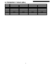
SSG Frequency: 39.875 MHz
24
KX-TC1205RUB / KX-TC1205RUW / KX-TC1205RUS / KX-TC1205RUF