


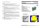

Plan View of TX802RTD Adjustments (Pt100 only)
1
2
3
4
5
6
ON
S1
Zero
OFF ON
Gain = 1 Gain = 0
Gain = 2 Gain = 0
Gain = 4 Gain = 0
Gain = 8 Gain = 0
Gain = 16 Gain = 0
Gain = 32 Gain = 0
OFF ON
Gain = 1 Gain = 0
Gain = 2 Gain = 0
Gain = 4 Gain = 0
Gain = 8 Gain = 0
Gain = 16 Gain = 0
Gain = 32 Gain = 0
S2
Span
S3
Function
1
2
3
4
ON
OFF ON
- Ve Offset + Ve Offset
Celsius Fahrenheit
Upscale Break Downscale
Break
1
2
3
4
5
6
ON
25 Turn Trimpot for ZERO ±10%
25 Turn Trimpot for SPAN ±10%
Input Terminals
Power Supply Terminals
LED Indication of Loop Current.
1 A
2 B
3 B
+
-
Examples of Input Connection.
Input
E.g. Loop Indicator,
With 4~20mA Input.
Terminations.
Input 1 A
2 B
3 B
Output 4 +mA
5 -mA
6 mV TEST
Output
T 6
- 5
+ 4
8~40Vdc
Power Supply
(Typ. 24Vdc.)
-
+
ZERO SPAN
2 Wire RTD OR 3 Wire RTD
1 A
2 B
3 B
Input
Link 2 & 3
+ mV -
2000V Isolation Barrier
40~200mV Test Signal
TX802RTD Specifications.
RTD Input CU10 RTD (3 Wire Type) Standard.
Sensor Current = 0.8mA.
Lead Wire Resistance = 10Ω/Wire Max.
Field Programmable Zero: -200C (-400F) to 200C (400F). (TX802RTD Only.)
Field Programmable Span: 20C (40F) to 400C (800F). (TX802 RTD Only.)
Suitable for 2 Wire Connection. (Offset Calibration needed.)
Other Types of RTD Available. JIS Pt100, Pt250, Pt500,
Pt1000, CU10, CU100, Ni100 or specify.
Output -mA 2 wire 4~20mA. (Loop Powered.)
-mV 40~200mV µ 4~20mA. (Indicative Test Signal Only.)
Other Output Voltages Available. e.g. 1~5V.
Power Supply 8~40Vdc.
Supply Voltage Sensitivty <±0.005%/V FSO.
Output Load Resistance 800W @ 24Vdc. (50W/V Above 8Vdc.)
Maximum Output Current Limited to <28mA.
Sensor Fail -Upscale 23mA Min.
-Downscale 3.6mA Max.
Accurate to <±0.1% FSO Typical.
Linearity & Repeatability <±0.1% FSO Typical.
Ambient Drift <±0.02%/C FSO Typical.
Noise Immunity 125dB CMRR Average. (2.0kVac RMS Limit.)
R.F. Immunity <1% Effect FSO Typical.
Isolation Voltage 2.0kVac\dc Input to Output for 60sec.
Response Time 200msec Typical. (10 to 90% 50msec Typical.)
Operating Temperature 0~70C.
Storage Temperature -20~80C.
Operating Humidity 90%RH Max. Non-Condensing.
Construction 6.6 Polyamide Thermoplastic Rail Mount Enclosure.
Note 1. Specifications based on Standard Calibration Unit, unless otherwise specified.
Note 2. Due to ongoing research and development, designs, specifications, and documentation are subject to change without notification.
No liability will be accepted for errors, omissions or amendments to this specification.
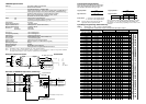
Input Range C
(Put S5-2 OFF)
Input Range F
(Put S5-2 ON)
S1-Zero S2-Span S3-Function
1 2 3 4 5 6 1 2 3 4 5 6 1 2 3 4
0~20C 0~40F 1 1 1 1 1 1 1 1 0 0 0 0 X
0~25C 0~50F 1 1 1 1 1 1 1 1 1 1 0 0 X
0~30C 0~60F 1 1 1 1 1 1 1 1 1 0 1 0 X
0~40C 0~80F 1 1 1 1 1 1 1 0 0 0 0 1 X
0~50C 0~100F 1 1 1 1 1 1 1 1 1 0 0 1 X
0~60C 0~120F 1 1 1 1 1 1 1 1 0 1 0 1 X
0~70C* 0~140F* 1 1 1 1 1 1 0 1 1 1 0 1 X
0~75C 0~150F 1 1 1 1 1 1 1 1 1 1 0 1 X
0~80C 0~160F 1 1 1 1 1 1 0 0 0 0 1 1 X
0~90C* 0~180F* 1 1 1 1 1 1 0 1 0 0 1 1 X
0~100C 0~200F 1 1 1 1 1 1 1 1 0 0 1 1 X
0~110C 0~220F 1 1 1 1 1 1 0 0 1 0 1 1 X
0~120C 0~240F 1 1 1 1 1 1 1 0 1 0 1 1 X
0~125C* 0~250F* 1 1 1 1 1 1 1 0 1 0 1 1 X
0~150C 0~300F 1 1 1 1 1 1 1 1 1 0 1 1 X
0~200C 0~400F 1 1 1 1 1 1 1 0 0 1 1 1 X
0~250C* 0~500F* 1 1 1 1 1 1 0 1 0 1 1 1 X
0~300C 0~600F 1 1 1 1 1 1 1 1 0 1 1 1 X
0~400C 0~800F 1 1 1 1 1 1 0 0 1 1 1 1 X
0~600C 0~1200F 1 1 1 1 1 1 1 0 1 1 1 1 X
-10~10C -20~20F 1 0 1 1 1 1 1 1 0 0 0 0 1
-10~20C -20~40F 1 0 1 1 1 1 1 1 1 0 1 0 1
-10~40C -20~80F 1 0 1 1 1 1 1 1 1 0 0 1 1
-20~20C -40~40F 1 1 0 1 1 1 1 0 0 0 0 1 1
-20~30C -40~60F 1 1 0 1 1 1 1 1 1 0 0 1 1
-25~25C -50~50F 0 1 0 1 1 1 1 1 1 0 0 1 1
-25~50C -50~100F 0 1 0 1 1 1 1 1 1 1 0 1 1
-30~20C -60~40F 1 0 0 1 1 1 1 1 1 0 0 1 1
-50~50C -100~100F 1 0 1 0 1 1 1 1 0 0 1 1 1
-50~100C -100~200F 1 0 1 0 1 1 1 1 1 0 1 1 1
-50~150C -100~300F 1 0 1 0 1 1 1 0 0 1 1 1 1
-100~100C -200~200F 1 1 0 1 0 1 1 0 0 1 1 1 1
-100~200C -200~400F 1 1 0 1 0 1 1 1 0 1 1 1 1
-200~200C -400~400F 1 1 1 0 1 0 0 0 1 1 1 1 1
-200~400C -400~800F 1 1 1 0 1 0 1 0 1 1 1 1 1
20~40C 40~80F 1 1 0 1 1 1 1 1 0 0 0 0 0
50~100C 100~200F 1 0 1 0 1 1 1 1 1 0 0 1 0
50~150C 100~300F 1 0 1 0 1 1 1 1 0 0 1 1 0
100~200C 200~400F 1 1 0 1 0 1 1 1 0 0 1 1 0
100~500C 200~1000F 1 1 0 1 0 1 0 0 1 1 1 1 0
Input Programming Pt100 only
If the input range is not listed in the programming
table, use the following formulae to work out the
Zero and Span DIP switch settings for gain.
deg C Span Gain = 1200 deg F Spain Gain = 2400
deg C High - deg C Low deg F High - deg F Low
deg C Zero Gain = deg C Low deg F Zero Gain = deg F Low
5 10
If Zero Gain is 1/ +ve Put S3-1 OFF (Positive Offset)
2/ -ve Put S3-1 ON (Negative Offset)
Note: Enter the Zero or Span gain value into the
appropriate Zero or Span DIP switch.
Input Range Programming Table Pt100 only.
Notes:1/ Switch status 1 = ON, 0 = OFF, X = DON'T CARE.
2/ Input ranges with '*' beside them require more adjustment by the Span trimpot.
SET TO '0' FOR CELCIUS. SET TO '1' FOR FAHRENHEIT.
Set to '0' for UPSCALE Sensor Break. Set to '1' for DOWNSCALE Sensor
Break.
TX802RTD ONLY
Set to '1' for UPSCALE Sensor Break. Set to '0' for DOWNSCALE Sensor
Break.
So if a gain value of 28 is required, put DIP switch No's 3, 4, 5 OFF
(ie, gains of 4 + 8 + 16 = 28) and all the other DIP switches ON.
Dip switches are accessed by seperating the two halves of the
enclosure
Gain Value 1 2 4 8 16 32
DIP Switch No. 1 2 3 4 5 6