


Quality Assurance Programme.
The modern technology and strict procedures of the ISO9001 Quality Assurance Programme applied during design,
development, production and final inspection grant the long term reliability of the instrument.
TX802RTD(F) CU10-F-2
Transmitter.
Isolating Linearised, 3 Wire RTD
Input, to 4~20 Output
Loop Powered Transmitter.
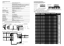
Graph Of Maximum Load Enclosure Dimensions.
Versus Power Supply.
Maximum Load
(Ω)
0
1000
800
1200
600
400
200
1400
1600
128 16 20 24 28 32 36 40
Power Supply (Vdc)
22.5
85.5
90.5
93.0
79.0
Features.
l CU10 input.
l Isolated Input to Output 2.0kV
l Field Programmable Input Ranges. TX802RTD
l High Accuracy.
l Linear With Temperature
l 40~200mV Output Test Signal.
l LED Indication of Loop Current.
l Low Cost.
l Compact DIN Rail Mount Enclosure.
l Available Standard or Special Calibration.
l Reverse Polarity Protection.
l Corrosion Proofed Circuit Board & Components
by Isonel 642. (Except Terminals & DIP Switches)
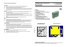
The Proper Installation & Maintenance.
MOUNTING.
(1) Mount in a clean environment in an electrical cabinet on DIN or EN mounting rail.
(2) Do not subject to vibration or excess temperature or humidity variations.
(3) Avoid mounting in cabinets with power control equipment.
(4) To maintain compliance with the EMC Directives the transmitter must be mounted in a fully enclosed
steel cabinet. The cabinet must be properly earthed, with appropriate input \ output entry points,
filtering, and cabling.
WIRING.
(1) All cables should be good quality overall screened INSTRUMENTATION CABLE with the screen
earthed at one end only.
(2) Signal cables should be laid a minimum distance of 300mm from any power cables.
(3) For 2 wire current loops Austral Standard Cables B5102ES is recommended. For 3 wire transmitters
and RTD's Austral Standard Cables B5103ES is recommended.
(4) It is recommended that you do not ground current loops and use power supplies with ungrounded
outputs.
(5) Lightning arrestors should be used when there is a danger from this source.
(6) Refer to diagrams for connection information.
RTD'S.
(1) Avoid locating the RTD where it will be in a direct flame.
(2) Locate it where the average temperature will be measured. It should be representative of the mass.
(3) Immerse the RTD far enough so that the measuring point is entirely in the temperature to be
measured; nine to ten times the diameter of the protection tube is recommended. Heat that is
conducted away from the measuring point causes an error in reading.
COMMISSIONING.
(1) Once all the above conditions have been carried out and the wiring checked apply power to the
transmitter loop and allow five minutes for it to stabilize.
(2) Due to differences in cable resistance in the RTD legs or errors within the RTD itself a small zero error
may occur (usually less than 0.5C). To remove this error use a calibration standard RTD at the
same immersion depth and adjust the Zero trimpot in the top of the transmitter enclosure with a small
screwdriver, until the two levels agree. (Clockwise to increase the output reading and anticlockwise
to decrease the output reading)
MAINTENANCE.
(1) Check RTD's in place - with a calibration RTD at the same immersion depth.
(2) Do it regularly - at least once every 6 months.
(3) Replace defective protection tubes - even if they look good they may not be air or gas tight.
(4) Check cables entering the RTD sensor head.