


12 Chapter 3 BST Doorphone Installation
NN40010-302
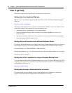
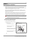
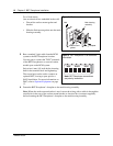
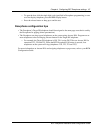
For a flush mount:
(into an electrical box embedded in the wall)
• Discard the surface mount gasket and
bracket.
• Slide the flush mount gasket onto the main
housing assembly.
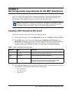
3 Run a standard 3-pair cable from the BCM
system to the BST Doorphone location.
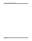
Use one pair to connect the
''KSU'' terminals
of the BST Doorphone to a reserved station
module port on the BCM system.
Strip wires 6 mm (1/4 inch) before inserting
them in the terminal block and tightening.
The second pair can be used to connect an
optional DOC, leaving a spare pair for a
SAPS installation. For more information on
DOC, refer to Optional Equipment on page
13.
4 Fasten the BST Doorphone’s faceplate to the main housing assembly.
Note: When the surface mount bracket is used, secure the wiring with a cable tie through the
round holes in the rear of the surface mount bracket or electrical box (customer supplied),
before fastening the BST Doorphone’s faceplate to the main housing assembly.
Flush mount
gasket
Main housing
assembly
Faceplate
Wall
Figure 2 Flush mount
KSU SAPS DOC
Note: BST Doorphone connections
are polarity insensitive.
Figure 3 BST Doorphone TCM connector
screw block