


11
BST Doorphone Installation and Configuration Guide
Chapter 3
BST Doorphone Installation
The BST Doorphone can be mounted in a standard recessed double-gang electrical box for flush
mounting or surface mounted using the optional surface mount bracket. Mount the BST
Doorphone at shoulder height (approximately 5 ft.) in the absence of other specifications, such as
compliance with local handicapped access regulations, if required.
Select a location for the BST Doorphone within 300 m (1000 ft.) of the BCM system. This
distance can be increased to 780 m (2600 ft.) with the connection of a Station Auxiliary Power
Supply (SAPS) to a BST Doorphone.
The BST Doorphone is suitable for exposure to weather; however, care must be taken to ensure
holes or recesses provided for the BST Doorphone are properly sealed to prevent water from
entering the wall in exposed locations. Gaskets are supplied for both flush and wall mount
installations. No gasket is required between the BST Doorphone and surface mount bracket.
Wire and mount a BST Doorphone
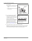
1 Remove the BST Doorphone’s faceplate.
2 Determine if you want a flush or surface mount installation.
For a surface mount:
• Discard the flush mount gasket.
• Verify the correct orientation of the
surface mount gasket.
• Thread the wires through the center hole,
then through the surface mount bracket.
• Fasten the surface mount bracket at the
desired location on the wall.
OR
Caution: You must install protection devices when wiring between the BST Doorphone
and the BCM system is routed outside a building, such as aerial or buried cable. Protection
devices must be installed at each end of the exposed cable. Nortel recommends the ITW
LINX MP1A-90-27 secondary protector for this purpose.
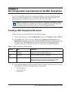
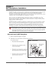
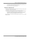
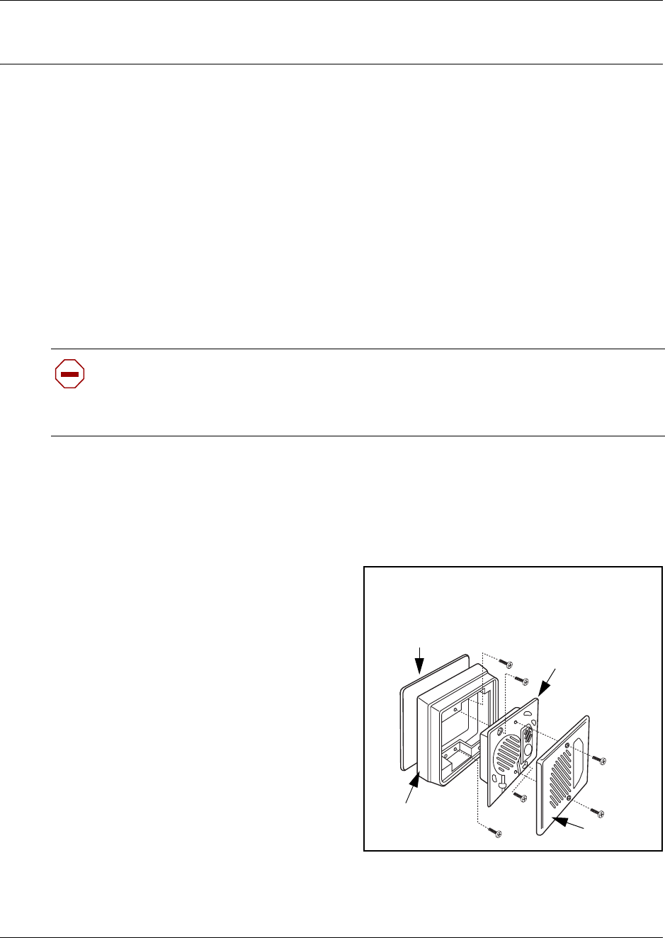
Surface mount
bracket
Main housing
assembly
Faceplate
Surface mount gasket
Figure 1 Surface mount