


– 6 –
INTRODUCTION
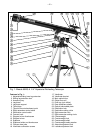
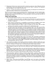
This manual details the set-up, operation, specifications and optional accessories of the Meade 60EQ-A 2.4"
(60mm) Equatorial Refracting Telescope.
UNPACKING AND ASSEMBLY
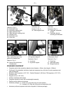
1. Remove and identify the telescope’s components, using the listing above.
2. Attach the 3 aluminum tripod legs (
6, Fig. 1) to the base of the altazimuth mount (7, Fig. 1) with the 3
leg braces supports (5, Fig. 1) facing inward. Three bolts each about 2.5"" long, with washers and wing
nuts (42, Fig. 7), are provided for this purpose in a hardware package. Stand the telescope upright,
spreading the tripod legs evenly apart so that the accessory tray can be positioned to attach to the 3 leg
braces.
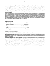
3. Use the provided 3 short screws, washers and bolts to attach the accessory tray (
3, Fig. 1) to the tripod.
Line up one of the leg braces (
4, Fig. 1) between the opening of one of the tripod leg brace supports (5,
Fig. 1) on the tripod so that one of the short screws will be able to pass through the holes of the leg
brace support and the leg brace. Using a Phillips-head screwdriver, thread one of the short screws
through the hole. Place a washer on the other end, followed by the matching nut. Tighten to a firm feel.
Repeat this procedure until all 3 leg braces are mounted on the 3 leg brace supports. See
Fig. 6.
4. To attach the accessory tray (3, Fig. 1) to the leg braces (4, Fig. 1), place the round accessory tray over
the over mounting bolt hole (36, Fig. 3). Threading the attachment knob into the the mounting hole on
top of the tray and turning the knob clockwise. Tighten to a firm feel, but do not overtighten—you will
need to remove the tray if you wish to collapse the tripod. To remove the tray, just rotate the knob
counterclockwise and remove the knob. You can then lift and remove the tray.
5. Extend the sliding center portion of the adjustable height tripod leg (
1, Fig. 1) to the desired length for
all 3 legs. Lock the tripod legs by tightening the leg lock thumbscrew (2, Fig. 1) to a firm feel.
6. Holding the counterweight (28, Fig. 1) firmly in one hand, slip the counterweight onto the counterweight
shaft (
30, Fig. 1). Attach the counterweight and counterweight shaft, by supporting the unlocked
counterweight firmly in one hand while threading the counterweight shaft into the base of the Declination
axis of the telescope’s equatorial mount (see position in Fig. 1). Once firmly attached, slide the
counterweight about 2 inches from the bottom of the counterweight shaft and secure it in place with the
counterweight lock (
29, Fig. 1) of the counterweight. Note: If the counterweight ever slips, the secured
threaded safety washer/screw (31, Fig. 1) will not let the weight slide entirely off the counterweight shaft.
Be certain that this safety washer/screw is always in place.
7. Attach the flexible cables (8, Fig. 1) and (9, Fig. 1), as shown. These cables are secured in place with
a firm tightening of the thumbscrews located at the attachment ends of each cable.
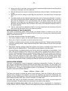
8. Tilt the polar axis (40, Fig. 2) of the telescope to roughly a 45° angle with the horizon. This tilt is
accomplished by first loosening the latitude adjustment lock (
33, Fig. 1), adjusting the mount and firmly
re-tightening the latitude control lock.
9. Remove the optical tube attachment thumbscrews (34, Fig. 3) from the optical tube mounting bolts that
are on the underside of the main optical tube (19, Fig. 1). Then lay the telescope optical tube assembly
onto the saddle plate (
23, Fig. 1) passing the mounting bolts through the holes in the saddle of the
mount. Re-attach the attachment thumbscrews to the mounting bolts, and tighten to a firm feel. See Fig.
5. Be sure the focuser portion of the optical tube is on the same side of the saddle as the Declination
control cable (
9, Fig. 1).
10. Attach the viewfinder bracket (18, Fig. 1) to the telescope using the 2 thumbscrews provided (37, Fig.
4). The bracket fits over the two small bolts near the focus knob (10, Fig. 1). Thread the thumbscrews
over the bolts and tighten to a firm feel. Slide the Viewfinder tube into the bracket and loosely tighten
the tube. See “Aligning the Viewfinder” below.
11. Insert the diagonal mirror (
12, Fig. 1) into the focuser drawtube (15, Fig. 1) and the 25mm eyepiece (13,
Fig. 1
) into the diagonal mirror. Secure each in place with a moderate tightening of the respective
thumbscrews.
The telescope is now completely assembled. Before it can be affectively used, however, the viewfinder (17,
Fig. 1) must be aligned with the main telescope.