


6 © MARMITEK
INSTALLATION
MAKE SURE THE MAINS ELECTRICITY IS SWITCHED OFF BEFORE INSTALLING THE MODULE!
The module must be installed by a qualified electrician!
The FD10 Phase Couplers/Filters can be placed directly after the main switch of the installation.
In order to connect the FD10 properly, phase (L) and null (N) must be available. If multiple
Filters are used in a multiple phase system, the Couplers/Filters must be connected to each
other via a single wire connection.
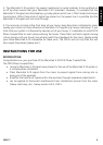
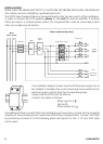
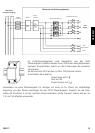
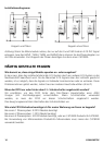
The installation diagram shows how the FD10 phase coupler has to
be installed: in between the current remaining mains switch for the
electrical system and the fuses for the separate groups.
Simply click the FD10 onto the DIN rail.
Connect the cables as follows:
Phase input to (L )
Null to (N)
Phase output to (L )
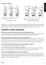
Use additional Phase Couplers/Filters for installations with more than 1 phase. For the complete
coupling of three phases you will need three FD10 Phase Couplers/Filters. Connect the filters
by connecting connector K to the following phase (see figure). For this, a 1.5 mm² shift cable
can be used.
Mains
power system
Meter cupboard (fuse box)
Main fuse
Meter
Mains
switch
FD10 phase coupler
Group fuse
X-10
signal
Oven
Dishwasher
Basement