


2
4 Visual Feedback
On the AE2000Plus and AE1000Plus systems, a text prompt will be shown on the system
display for guidance.
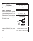
On the AM3Plus system, the LED on the PBUS keypad will be used to provide visual
feedback. A long “amber” LED will signify an error, two short fl ashing green LED will
signify the successful entry of a programming fi eld, and three short fl ashing green LED
will signify the successful entry of a complete programming step.
5 Audible Feedback
When entering data, one long beep will signify an error, two short beeps will signify the
successful entry of a programming fi eld, and three short beeps will signify the successful
entry of a complete programming step.
One short beep will signify the entry of the asterisk “∗” key.
6 Switching to Normal Network Operation Mode
In Local Programming mode, each Controller operates individually in a non-network
confi guration.
In order for the installer to be able to remotely switch the installation back to normal
network operation mode, each unit needs to have the node address set correctly and the
network cables wired during Local Programming mode.
AccessBase2000 System
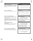
For AccessBase2000 confi guration, when the installer presses the “ON/OFF-line with
installation” button from AccessBase 2000 application, AccessBase 2000 application will
be able to detect all nodes that are connected to the network. After the installation is
connected, the database that was entered while in Local Programming mode will not
be erased and Local Programming will still be enabled. This feature maybe used by the
installer to verify that the network cabling is correct without erasing the locally programmed
database. When the “Program network” button is pressed, the locally programmed
database will be erased and Local Programming will be disabled.
AXNET System
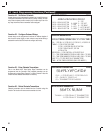
For AXNET confi guration, when the installer remotely connects to the master node via a
PPP connection, the master node’s database that was entered via Local Programming
will be erased and Local Programming will be disabled.
After the master node’s database is erased and initialized, it needs to be confi gured with
the network connection topology. This can be done by using a Web Browser connected to
the master node with URL http://192.6.94.2; then setup the correct network topology via
Global Settings -> Networking and select the correct Network Topology Confi guration.
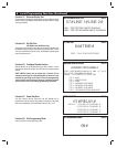
As an example, if Network Topology 2 is selected, Node 2’s database that was entered via
Local Programming will be erased and its Local Programming will be disabled.
The browser will display a dialog box indicating that “Node 2 is now Inaccessible”.
Inaccessible nodes can only be reactivated by resubmitting previous commands via the
Network Status menu. The installer will need to acknowledge this message and then go
to Controllers -> My Controller 2 and click the Refresh button to refresh Node 2’s status
and regain the accessibility to Node 2.
If the PPP connection to the master node is via a modem, the installer will need to
disconnect the PPP connection to the master node so that the master node can use the
phone line to connect to the other nodes on the network.
7 Re-enabling Local Programming
Local Programming may be re-enabled when Data Flash is erased by using UP & DOWN
switches on the motherboard to select and activate CL option (see Page 1).