


Technical Specifications
KRAMER ELECTRONICS, LTD.
4
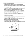
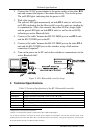
2. Connect the 5V DC power adapter to the power socket on the other BT-1
unit and connect the adapter to the mains electricity. Turn on the power.
The red LED lights, indicating that the power is ON.
3. Wait a few seconds.
The yellow LED lights momentarily on both BT-1 units (as well as the
red LED), indicating that the Bluetooth® controller units are standing-by
to communicate. After a few seconds, the yellow LED no longer lights
and the green LED lights on both BT-1 units (as well as the red LED),
indicating an active Bluetooth link.
4. Connect a flat cable
1
between the RS-232 DB9F port on one BT-1 unit
and the RS-232 DB9 port on the PC.
5. Connect a flat cable
1
between the RS-232 DB9F port on the other BT-1
unit and the RS-232 DB9 port on the switcher, using a Null-modem
connection if required
2
.
6. Turn on the power on the PC and on the switcher to communicate via the
active Bluetooth link
3
.
Figure 2: BT-1 Bluetooth® controller Setup
5 Technical Specifications
Table 2: Technical Specifications of the BT-1 Bluetooth® controller
Control: DB9F connector
LEDs: Red (power ON), yellow (standing-by to communicate), green (active Bluetooth link)
Dimensions: 6.5 cm x 3.6 cm x 5 cm (2.56" x 1.42" x 1.97", W, D, H)
Power Source: 5V DC
Weight: .057 kg (0.13lbs.) approx.
Accessories: Power supply, null-modem adapter
Serial Interface: Speed rate: 9600bps, no flow control, 8 bit, no parity, 1 stop bit
1 Straight one-to-one uncrossed connections
2 That is, if connecting that switcher to a PC would require a Null-modem adapter
3 If no data is transferred, disconnect the 5V DC power adapters from both BT-1 units and then reconnect them. If the
problem persists, disconnect both BT-1 units—from the PC and from the switcher. Verify proper operation by connecting the
PC and the switcher directly via a RS-232 cable connection