


Using the Bluetooth® controller
3
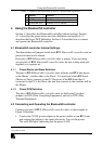
Table 1: Features and Functions of the BT-1 Bluetooth® controller
# Feature Function
1 Display Window Displays the status of the LEDs
2 5V DC Power Socket +5V DC connector for powering the unit
3 RS-232 DB9F Port Connects to PC or switcher
4 Using the Bluetooth® controller
Section 4.1 describes the Bluetooth® controller internal settings. Section
4.1.1 describes the preset master and slave definition and section 4.1.2
describes the Preset DCE Definition. Section 4.2 describes how to connect
and operate the Bluetooth® controller.
4.1 Bluetooth® controller Internal Settings
The dipswitches and jumpers inside each BT-1 Bluetooth® controller unit are
preset and must not be altered.
Each pair of BT-1 Bluetooth® controller units is unique. If you are using
several pairs of BT-1 Bluetooth® controller units, be sure to keep each pair
together, as a separate set.
4.1.1 Preset Master and Slave Definition
The pair of BT-1 Bluetooth® controller units includes one BT-1 unit preset
as the Master
1
, and the other as the Slave
2
. It is irrelevant which BT-1 unit
(Master or Slave) connects to the PC. However, if the BT-1 unit that is
connected to the PC is the Slave, the unit that connects to the switcher will be
the Master.
4.1.2 Preset DCE Definition
The pair of BT-1 Bluetooth® controller units are both preset (via their
jumpers) as DCE (Data Computing Equipment) and not as DTE (Data
Terminal Equipment).
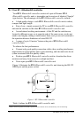
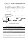
4.2 Connecting and Operating the Bluetooth® controller
Connect your pair of BT-1 Bluetooth® controller units, as the example in
Figure 2 illustrates:
1. Connect the 5V DC power adapter to the power socket on one BT-1 unit
and connect the adapter to the mains electricity. Turn on the power.
The red LED lights, indicating that the power is ON.
1 DIPS 1, 2 and 4 are OFF and DIP 3 is ON
2 All 4 DIPS are OFF