


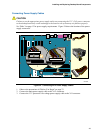
Installing and Replacing Desktop Board Components
41
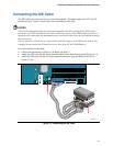
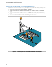
Connecting USB 2.0 Headers
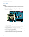
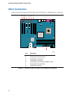
Before connecting the USB 2.0 headers, observe the precautions in "Before You Begin" on
page
23. See Figure 20, D on page 39 for the location of the black USB 2.0 headers. Table 7
shows the pin assignments for the USB 2.0 headers.
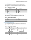
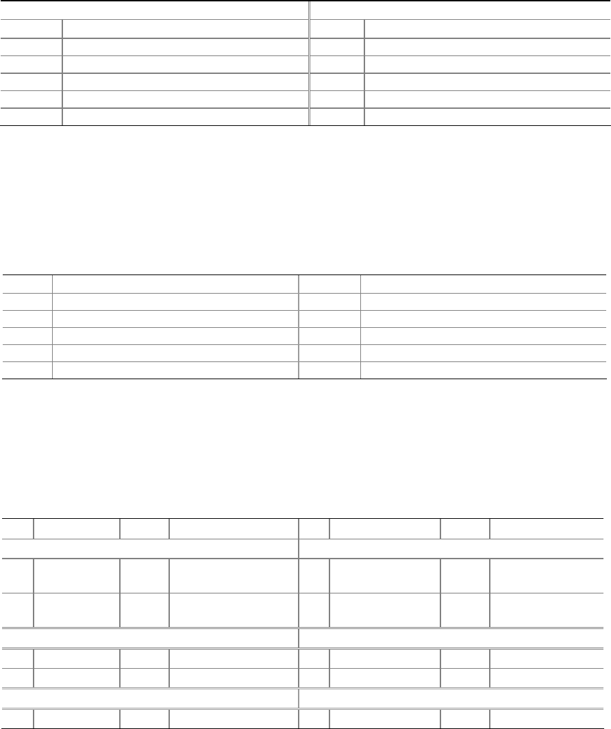
Table 7. USB 2.0 Header Signal Names
USB Port A USB Port B
Pin Signal Name Pin Signal Name
1 Power 2 Power
3 D- 4 D-
5 D+ 6 D+
7 Ground 8 Ground
9 Key 10 No connect
Note: USB ports may be assigned as needed.
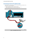
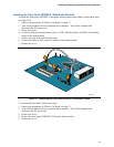
Connecting IEEE 1394a Headers
Before connecting the IEEE 1394a headers, observe the precautions in "Before You Begin" on
page
23. See Figure 20, E on page 39 for the location of the blue IEEE 1394a headers.
Table 8 shows the pin assignments for the headers.
Table 8. IEEE 1394a Header Signal Names
Pin Signal Name Pin Signal Name
1 TPA1+ 2 TPA1-
3 Ground 4 Ground
5 TPA2+ 6 TPA2-
7 +12 V 8 +12 V
9 Key (no pin) 10 Ground
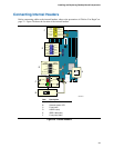
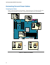
Connecting the Front Panel Header
Before connecting the front panel header, observe the precautions in "Before You Begin" on
page
23. See Figure 20, C on page 39 for the location of the multi-colored front panel header.
Table 9 shows the pin assignments for the front panel header.
Table 9. Front Panel Header Signal Names
Pin Signal In/Out Description Pin Signal In/Out Description
Hard Drive Activity LED (Orange) Power LED (Green)
1 HD_PWR Out Hard disk LED pull-
up (330 Ω) to +5 V
2 HDR_BLNK_GRN Out Front panel green
LED
3 HDA# Out Hard disk active LED 4 HDR_BLNK_YEL Out Front panel yellow
LED
Reset Switch (Purple) On/Off Switch (Red)
5 Ground Ground 6 SWITCH_ON# In Power switch
7 FP_RESET# In Reset switch 8 Ground Ground
9 N/C Not connected 10 No pin No pin