


Desktop Board Features
17
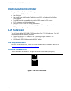
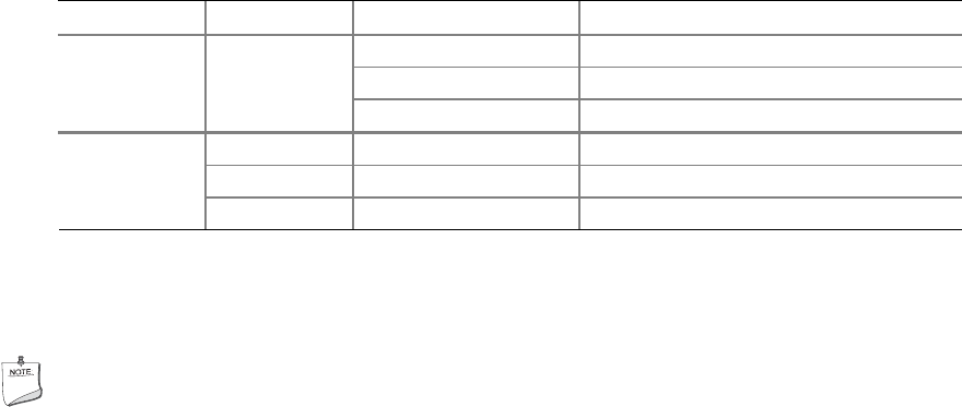
Two LEDs are built into the RJ-45 LAN connector. Table 4 describes the LED states when the
board is powered up and the 10/100/1000 Gigabit Ethernet LAN subsystem is operating.
Table 4. RJ-45 10/100/1000 Gigabit Ethernet LAN Connector LEDs
LED LED Color LED State Indicates
Left Off LAN link is not established
Green
On LAN link is established
Blinking LAN activity is occurring
N/A Off 10 Mb/s data rate
Green On 100 Mb/s data rate
Right
Yellow On 1000 Mb/s data rate
Hi-Speed USB 2.0 Support
NOTE
Computer systems that have an unshielded cable attached to a USB port might not meet FCC
Class B requirements, even if no device or a low-speed USB device is attached to the cable.
Use a shielded cable that meets the requirements for a full-speed USB device.
The desktop board supports up to eight USB 2.0 ports via ICH7R; four ports routed to the back
panel and four routed to two internal USB 2.0 headers. USB 2.0 ports are backward compatible
with USB 1.1 devices. USB 1.1 devices will function normally at USB 1.1 speeds.
USB 2.0 support requires both an operating system and drivers that fully support USB 2.0 transfer
rates. Disabling Hi-Speed USB in the BIOS reverts all USB 2.0 ports to USB 1.1 operation. This
may be required to accommodate operating systems that do not support USB 2.0.
Enhanced IDE Interface
The ICH7R’s IDE interface handles the exchange of information between the processor and
peripheral devices like hard disks, CD-ROM drives, and Iomega Zip* drives inside the computer.
The interface supports:
• Up to two IDE devices (such as hard drives)
• ATAPI-style devices (such as CD-ROM drives)
• Older PIO Mode devices
• Ultra DMA-33 and ATA-66/100 protocols
• Laser Servo (LS-120) drives
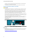
Serial ATA
The desktop board supports four Serial ATA channels via ICH7R, connecting one device per
channel. Desktop boards with ICH7R support Intel Matrix Storage Technology (NCQ, Hot Plug,
RAID 0, 1, 10, 5, and Matrix RAID).