


Installing and Replacing Desktop Board Components
35
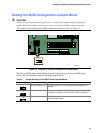
Installing a Front Panel Audio Solution
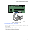
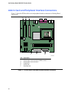
Figure 9-A shows the location of the front panel audio header. Table 7 shows the pin assignments
for the front panel audio header.
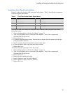
Table 7. Front Panel Audio Header Signal Names
Pin Signal Name Pin Signal Name
1 AUD-MIC 2 AUD-GND
3 AUD-MIC-BIAS 4 AUD-VCC
5 AUD-FPOUT-R 6 AUD-RET-R
7 HP-ON 8 KEY
9 AUD-FPOUT-L 10 AUD-RET-L
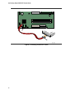
To install the cable that connects the front panel audio solution to the front panel audio header,
follow these steps:
1. Observe the precautions in “Before You Begin” on page 21.
2. Turn off all peripheral devices connected to the computer. Turn off the computer and
disconnect the AC power cord.
3. Remove the cover.
4. Locate the front panel audio header. Remove the two jumpers from the header to disable the
back panel audio connectors.
5. Install a correctly keyed and shielded front panel audio cable.
6. Connect the audio cable to the front panel audio solution.
7. Replace the cover.
To restore back panel operations, follow these steps:
1. Observe the precautions in “Before You Begin” on page 21.
2. Turn off all peripheral devices connected to the computer. Turn off the computer and
disconnect the AC power cord.
3. Remove the cover.
4. Remove the front panel audio cable.
5. Install a jumper on pins 5-6 (rear R channel).
6. Install a jumper on pins 9-10 (rear L channel).
7. Replace the cover.