


21
2 Installing and Replacing Desktop
Board Components
This chapter tells you how to:
•
Install the I/O shield
•
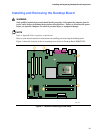
Install and remove the desktop board
•
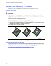
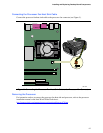
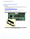
Install and remove a processor and memory
•
Connect the IDE and/or Serial ATA cable
•
Connect internal headers
•
Connect hardware control and power cables
•
Locate the add-in card and peripheral interface connectors
•
Set the BIOS configuration jumper
•
Clear passwords
• Identify back panel connectors
• Replace the battery
Before You Begin
WARNINGS
The procedures in this chapter assume familiarity with the general terminology associated with
personal computers and with the safety practices and regulatory compliance required for using
and modifying electronic equipment.
Disconnect the computer from its power source and from any telecommunications links,
networks, or modems before performing any of the procedures described in this chapter. Failure
to disconnect power, telecommunications links, networks, or modems before you open the
computer or perform any procedures can result in personal injury or equipment damage. Some
circuitry on the board can continue to operate even though the front panel power button is off.
CAUTION
Many of the internal and front panel connectors provide operating voltage (+5 V dc and +12 V dc,
for example) to devices inside the computer chassis, such as fans and internal peripherals. These
connectors are not overcurrent protected. Do not use these connectors for powering devices
external to the computer chassis. A fault in the load presented by the external devices could cause
damage to the computer, the interconnecting cable, and the external devices themselves.